CAD_1_2
by Tim Lueth & Laurans de Smedt, SG-Lib Toolbox: SolidGeometry 5.6 - Modeling function
Introduced first in SolidGeometry 2.4, Creation date: 2015-06-29, Last change: 2025-08-19
PUBLISHABLE EXAMPLE of Excercise CAD 1.2
Description
This function is an example how to solve the excercise 1.2 of the
"Rechnerintegrierte Produktentwicklung - CAD und CAD/CAM" (2015)
of Professor Dr.-Ing. Udo Lindemann
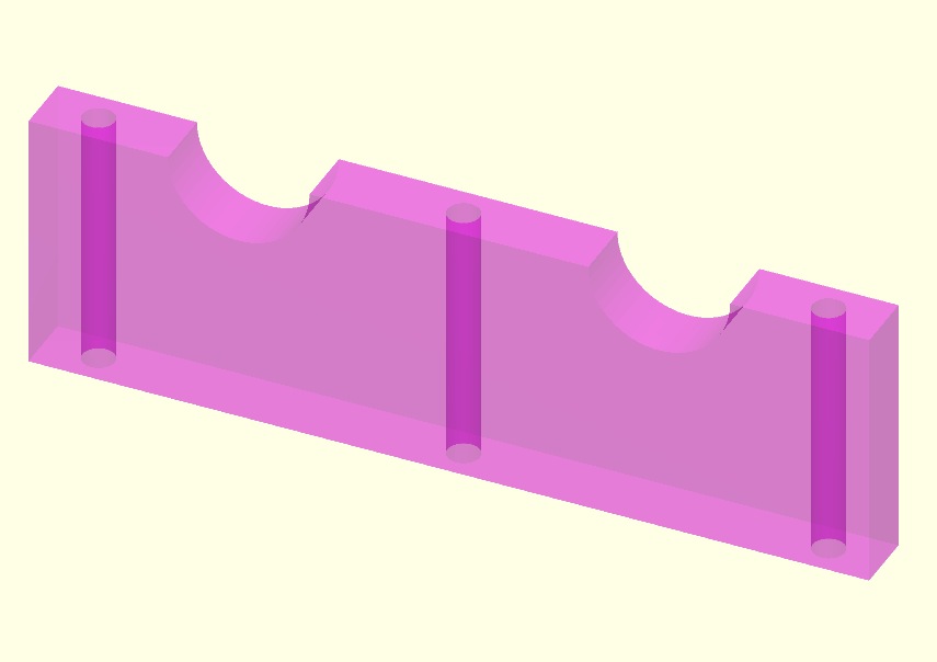
Example Illustration
Syntax
CAD_1_2
Copyright 2015-2025 Tim C. Lueth. All rights reserved. The code is the property of Tim C. Lueth and may not be redistributed or modified without explicit written permission. This software may be used free of charge for academic research and teaching purposes only. Commercial use, redistribution, modification, or reverse engineering is strictly prohibited. Access to source code is restricted and granted only under specific agreements. For licensing inquiries or commercial use, please contact: Tim C. Lueth
Algorithm (Workflow)
This algorithm is a MATLAB script designed to create a 3D model of a part using CAD techniques. The script is structured to define a 2D contour, extrude it into a 3D shape, and then modify it by subtracting cylindrical holes. Below is a detailed explanation of the algorithm and its parameters.
Input Parameters
- No explicit input parameters are required for this function as it is self-contained.
Algorithm Steps
- Initialize the environment by closing all figures and starting a timer with
close all and tic.
- Define the outer contour of the part as a rectangle with vertices at (0,0), (160,0), (160,50), and (0,50). This is stored in the variable
PL.
- Convert the defined polygon
PL into a closed polygon line using CPLofPL(PL).
- Create a new figure and set the view to a top-down perspective using
VLFLfigure and view(0,90).
- Plot the outer contour using
CPLplot(PL).
- Create a circular contour with a radius of 13.5 mm using
PLcircle(13.5) and store it in PLR.
- Subtract two circles from the rectangle at positions (40,50) and (120,50) using
CPLbool('-',PL,PLtransP(PLR,[x,y,0])).
- Plot the modified contour in blue using
CPLplot(PL,'b').
- Extrude the 2D contour into a 3D solid with a height of 12 mm using
SGofCPLz(PL,12) and set the view to an isometric perspective.
- Rotate the solid to a 'standing' position using
SGtransR(A,rotdeg(90,0,0)).
- Plot the solid using
SGplot(A).
- Create a cylindrical solid for drilling holes with a diameter of 6.1 mm and a height of 60 mm using
SGofCPLz(PLcircle(6.1/2),60).
- Center the cylindrical solid within the main solid using
SGincenter(B,A).
- Subtract the centered cylindrical solid from the main solid to create the first hole using
SGbool('-',A,B).
- Align the cylindrical solid to the left and right of the main solid and subtract to create the second and third holes using
SGalignleft(B,A,7.5) and SGalignright(B,A,7.5).
- Plot the cylindrical solid in green using
SGplot(B,'g') and set the view to an isometric perspective.
- Create a new figure for the final solid and set the view using
SGfigure(A) and view(-30,30).
- Add lighting to the plot using
VLFLplotlight(1,0.9).
- Stop the timer and display the elapsed time using
toc.
- Export the final 3D model to an STL file named 'CAD_1_2' using
SGwriteSTL(A,'CAD_1_2').
Algorithm explaination created using ChatGPT on 2025-08-19 07:37. (Please note: No guarantee for the correctness of this explanation)
Last html export of this page out of FM database by TL: 2025-09-21