SGcableclip

by Tim C. Lueth, SG-Lib Toolbox: SolidGeometry 5.6 - Parametric Design
Introduced first in SolidGeometry 5.3, Creation date: 2023-08-08, Last change: 2025-09-15
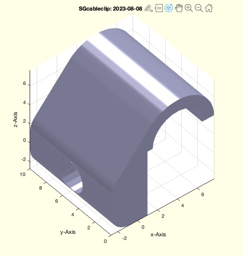
returns cableclip that can be fixed in 90 degree by a nail

Description

Tutorial function

See Also: SGbookwedge , SGhandrailclamp , SGmultisocketclamp

Example Illustration

 missing image of SGcableclip (BDW)

Syntax

SGcableclip([BDW])

Input Parameter

BDW: Nail length, Diameter of cable, wall thickness; default is [3 5 2]

Examples


SGcableclip([03 5 3])
SGcableclip([05 5 3])
SGcableclip([10 5 3])


Copyright 2023-2025 Tim C. Lueth. All rights reserved. The code is the property of Tim C. Lueth and may not be redistributed or modified without explicit written permission. This software may be used free of charge for academic research and teaching purposes only. Commercial use, redistribution, modification, or reverse engineering is strictly prohibited. Access to source code is restricted and granted only under specific agreements. For licensing inquiries or commercial use, please contact: Tim C. Lueth

Algorithm (Workflow)

This function, SGcableclip, is designed to create a cable clip that can be fixed at a 90-degree angle using a nail. It is part of the SolidGeometry library and was introduced in version 5.3. The function takes an optional input parameter, BDW, which is a vector containing three values: the nail length, the diameter of the cable, and the wall thickness. The default values for BDW are [3, 5, 2].

Input Parameters

Algorithm Steps

  1. Retrieve the input parameters using getfuncparams, with default values [3, 5, 2].
  2. Assign the values from BDW to variables B, D, and w.
  3. Create a square profile a with side length B using PLsquare.
  4. Create a circular profile b with diameter D using PLcircle.
  5. Combine profiles a and b using CPLunion with 'ontop' and 'right' alignment.
  6. Translate profile b relative to a using CPLtransrelCPL with 'ontop' and 'right' alignment.
  7. Create a buffer around the convex hull of the combined profile using CPLbuffer with a buffer distance of 1.2 mm.
  8. Add radial edges to the buffered profile using CPLradialEdges with 2 edges.
  9. Create a square profile f with dimensions based on the minimum and maximum of D and B, plus an additional buffer of 1.2 mm on each side.
  10. Subtract profile f from the radial-edged profile using CPLsubtract with 'alignright' and 'alignbottom' alignment.
  11. Subtract the translated circular profile b from the result.
  12. Extrude the resulting profile to create a 3D shape using SGofCPLextrude with a height of 10 mm along the y-axis.
  13. Create a cylinder P with diameter D and height 20 mm, rotate it by 90 degrees around the y-axis, and translate it to the origin using SGtrans0.
  14. Subtract the cylinder P from the extruded shape using SGsubtract with 'centery' alignment.
  15. If no output is requested, plot the resulting shape using SGfigure and SGplotalpha, and save it as an STL file using SGwriteSTL after rotating it by 90 degrees around the x-axis.
Algorithm explaination created using ChatGPT on 2025-08-19 07:09. (Please note: No guarantee for the correctness of this explanation)

Last html export of this page out of FM database by TL: 2025-09-21