SGclampCTtable
by Tim C. Lueth, SG-Lib Toolbox: SolidGeometry 5.6 - Parametric Design
Introduced first in SolidGeometry 5.2, Creation date: 2022-03-19, Last change: 2025-09-15
returns the solid geometry for a CT table clamp
See Also: PLclampCTtable
Example Illustration
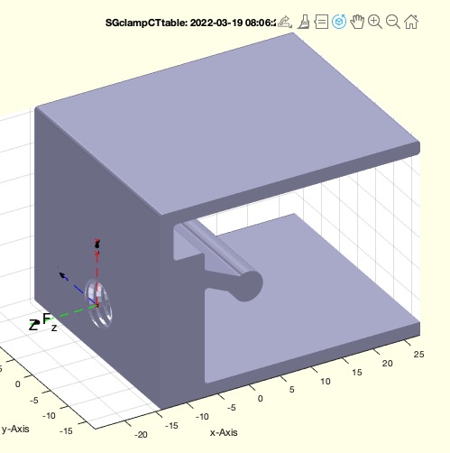
Syntax
SG=SGclampCTtable([LL,M,clpar])
Input Parameter
LL: | | Width of clamp |
M: | | Diameter of metric screw (positive core hole; negative nut); default is 0 |
clpar: | | same parameter as PLclampCTtable; default may be [40 3 0.5 3] |
Output Parameter
SG: | | Solid geometry including Frame at centered screw position |
Examples
SGclampCTtable(35,+8);
SGclampCTtable(35,-8);
Copyright 2022-2025 Tim C. Lueth. All rights reserved. The code is the property of Tim C. Lueth and may not be redistributed or modified without explicit written permission. This software may be used free of charge for academic research and teaching purposes only. Commercial use, redistribution, modification, or reverse engineering is strictly prohibited. Access to source code is restricted and granted only under specific agreements. For licensing inquiries or commercial use, please contact: Tim C. Lueth
Algorithm (Workflow)
This algorithm generates a solid geometry for a CT table clamp. It is part of the SG-Library and was introduced in SolidGeometry 5.2. The function takes three input parameters and returns a solid geometry object.
Input Parameters
- LL: Width of the clamp. Default value is 35 mm.
- M: Diameter of the metric screw. A positive value indicates a core hole, while a negative value indicates a nut. Default value is 0.
- clpar: Parameters for the clamp, similar to those used in PLclampCTtable. Default values are [40, 3, 0.5, 3].
Output
- SG: Solid geometry including a frame at the centered screw position.
Algorithm Steps
- Retrieve the input parameters using the
getfuncparams function. Default values are used if parameters are not provided.
- Call
PLclampCTtable to obtain the clamp parameters and the cross-sectional profile (CPL).
- Calculate the width
w using the second element of clpar and a constant value of 7.8.
- Set an offset length
ol to 0.1 mm.
- Generate the solid geometry by extruding the CPL along the y-axis using
SGofCPLextrude.
- Translate the solid geometry to center it using
SGtransP.
- Calculate the bounding box of the solid geometry using
BBofSG.
- Create a transformation matrix
T using TofPez to position the frame.
- Set the transformation matrix
T to the solid geometry using SGTset.
- If
M is not zero, perform the following:
- If
M is positive, create a cylinder using SGcylinder with diameter M and height w + 2 * ol.
- If
M is negative, create a nut using SGDIN13 with diameter M and height w + 2 * ol.
- Set the transformation matrix of the created geometry to identity using
SGTset.
- Subtract the created geometry from the solid geometry using
SGsubtract with alignment options.
- If no output is requested, plot the solid geometry using
SGfigure and SGTplotalpha, and write the geometry to an STL file using SGwriteSTL.
Algorithm explaination created using ChatGPT on 2025-08-19 07:14. (Please note: No guarantee for the correctness of this explanation)
Last html export of this page out of FM database by TL: 2025-09-21