by Tim C. Lueth, SG-Lib Toolbox: SolidGeometry 5.6 - Surfaces
Introduced first in SolidGeometry 5.0, Creation date: 2020-09-02, Last change: 2025-09-14
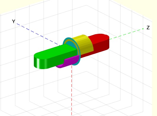
[SGN,T2,SGBB]=SGcutTcylindricblade([SG,T,ct,R,H])
SG: | Solid geometry | |
T: | Cutting plane x/y or empty for interactive selection | |
ct: | turn of cutting plane 'a', 's', 'c' | |
R: | [Radius blade-tickness starting angle]; default is [7 0.3 0] | |
H: | Height of cylindric blades and plate blade default is [10 0.08] |
SGN: | {Lower Part (Green) and Upper Part (Red)} | |
T2: | Frame T2 | |
SGBB: | Cutting Blade for visualization |
SGManipulatorLink; SG=ans; T=TofP([20 0 3]); tplot(T,20);
loadweb ADAM_A.mat; SGsurfaces(ADAM_A); A=ans; % Separate STL into limbs
SGcutTcylindricblade(SGManipulatorLink,'','a',10)
SGcutTcylindricblade(SGManipulatorLink,'','c',10)
SGcutTcylindricblade(SGManipulatorLink,'','s',10)