by Tim C. Lueth, SG-Lib Toolbox: SolidGeometry 5.6 - ENG-Components
Introduced first in SolidGeometry 4.3, Creation date: 2018-10-11, Last change: 2025-09-14
See Also: PLgearrackDIN
, SGgearpairDIN
, SGgearrackDIN
, CPLmotorshaft
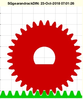
SGgearandrackDIN([m,z1,z2,R,h])
m: | module | |
z1: | teeth number of gear | |
z2: | teeth number of rack | |
R: | bore of gear | |
h: | height of gear and rack |
SGgearandrackDIN(1,32,12,5,10)
SGgearandrackDIN(1,32,12,CPLmotorshaft(5,3),10)This algorithm is designed to create a gear and gear rack combination using the SGgearandrackDIN function. It is part of the SolidGeometry library and was introduced in version 4.3. The function takes several input parameters to define the characteristics of the gear and rack.
getfuncparams function. Default values are provided if certain parameters are not specified:
m defaults to 1 if not provided.z1 defaults to 21 if not provided.z2 defaults to 10 if not provided.R defaults to an empty string if not provided.h defaults to m*6 if not provided.SGgearDIN function with the parameters m, z1, R, h, and an additional parameter 0 which might represent a specific configuration or option.SGgearrackDIN function with the parameters m, z2, an empty string, h, 1, and true. These additional parameters might represent specific configurations or options for the rack.SGtransR function with a rotation matrix rot(0,0,pi/2).SGtransP function with a translation vector [m*z1/2 -m*pi*z2/2 0]. This positions the rack relative to the gear.nargout==0), a new figure is created using SGfigure, and the view is set to a top-down perspective with view(0,90).SGplot function, with the gear in red ('r') and the rack in green ('g').