SGmodelLink3
by Tim C. Lueth, SG-Lib Toolbox: SolidGeometry 5.6 - Parametric Design
Introduced first in SolidGeometry 3.3, Creation date: 2017-01-11, Last change: 2025-08-19
retuns solid geometries for R linkages
See Also: SGmodelLink
, SGmodelJoint
, SGmodelNode
, SGmodelKeyhole
, SGmodelLink1
, SGmodelLink2
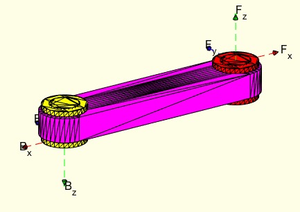
Example Illustration
Syntax
SGA=SGmodelLink3(L,lb,lf)
Input Parameter
Output Parameter
Copyright 2017-2025 Tim C. Lueth. All rights reserved. The code is the property of Tim C. Lueth and may not be redistributed or modified without explicit written permission. This software may be used free of charge for academic research and teaching purposes only. Commercial use, redistribution, modification, or reverse engineering is strictly prohibited. Access to source code is restricted and granted only under specific agreements. For licensing inquiries or commercial use, please contact: Tim C. Lueth
Algorithm (Workflow)
This function, SGmodelLink3, is designed to create solid geometries for R linkages. It takes three input parameters: L, lb, and lf. The output is a solid geometry object, SGA.
Input Parameters
- L: A vector or scalar representing the length or dimensions of the linkage. If L is a vector, its angle is calculated using atan2, and its magnitude is determined using the norm function.
- lb: Not explicitly used in the code, but likely represents a parameter related to the linkage's base.
- lf: Not explicitly used in the code, but likely represents a parameter related to the linkage's final or end part.
Algorithm Steps
- Initialize constants: slot, Ri, b, minw, olap, h, and b.
- Calculate derived parameters: Ra (outer diameter), Rd (drilling hole), and Rs (safety cap).
- Determine the angle phi if L is a vector, and calculate its magnitude.
- Use SGfigure to initialize a new figure for plotting.
- Create contours for the link using PLcircle and PLtransP functions, and plot them using CPLplot and PLplot.
- Combine the contours into a solid geometry using SGofCPLz and assign it to SGA.
- Create a solid for the bolt using SGofCPLz and SGtransP, and adjust its position with SGaddrelSG.
- Create a solid for the safety cap using SGofCPLz.
- Position the bolt and cap using SGtransP and assign colors to each solid (SGB, SGC, SGA).
- Plot the combined solids using SGTplot.
- Create transformation frames TB and TF using TofR and rot functions.
- Set the frames for SGA using SGTset.
- Concatenate the solids into a single object using SGcat2.
- Apply a rotation transformation to SGA using SGtransR.
- Plot the final assembly using SGTplot.
Algorithm explaination created using ChatGPT on 2025-08-19 07:46. (Please note: No guarantee for the correctness of this explanation)
Last html export of this page out of FM database by TL: 2025-09-21