by Tim C. Lueth, SG-Lib Toolbox: SolidGeometry 5.6 - Surfaces
Introduced first in SolidGeometry 5.2, Creation date: 2022-04-23, Last change: 2025-09-15
See Also: SGof2CPLzheurist
[EE,hE]=SGof2CPLtransition4FDM(CPLB0,CPLi,[rmin,alpha])
CPLB0: | Lower Contour | |
CPLi: | Higher Contour | |
rmin: | optional minimal angle | |
alpha: | optional transition angle; default is 50/180*pi |
EE: | Transition solid | |
hE: | height of EE in z |
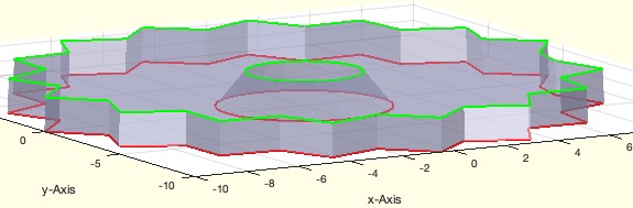
SGof2CPLtransition4FDM(CPLsubtract(PLstar(10),PLcircle(3)),CPLsubtract(PLstar(10),PLcircle(2)))This function, SGof2CPLtransition4FDM, is designed to create a transition solid between two contours to avoid support structures in FDM (Fused Deposition Modeling) 3D printing. Below is a detailed explanation of the algorithm and its parameters.
rmin and alpha using the getfuncparams function. If rmin is not provided, it is calculated using the PLcircleofPL function on CPLi.M to rmin.hE of the transition solid using the formula: hE = tan(alpha) * M / 2.EE using the SGof2CPLzheurist function, which takes buffered versions of CPLB0 and CPLi and the calculated height hE.SGfigure, CVLplots, and SGplotalpha functions.The function can be used as follows:
SGof2CPLtransition4FDM(CPLsubtract(PLstar(10),PLcircle(3)), CPLsubtract(PLstar(10),PLcircle(2)))
This example creates a transition solid between two star-shaped contours with circular subtractions.
Algorithm explaination created using ChatGPT on 2025-08-19 06:44. (Please note: No guarantee for the correctness of this explanation)