SGofpdemodel
by Tim C. Lueth, SG-Lib Toolbox: SolidGeometry 5.6 - FEM/PDE
Introduced first in SolidGeometry 4.2, Creation date: 2018-02-28, Last change: 2025-09-14
returns a solid geometry surface model of a pde model
Description
the tetrahedron models of the model.Mesh are used to create a tetrahedron triangulation. The freeboundary surface of this model is used to create the surface model.
In contrast to tetramesh, the tetrahedrons in 3D pde models have 11 vertices.
See Also: pdemodelofSG
, SGtetramesh
, SGremsurfpoints
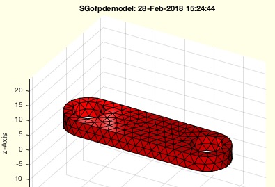
Example Illustration
Syntax
SG=SGofpdemodel(model)
Input Parameter
model: | | pde model created by pdemodelofSG |
Output Parameter
SG: | | Solud Geometry surface model |
Examples
A=SGlinkage(5,40,5)
model=pdemodelofSG(A,1)
SGofpdemodel(model)
Copyright 2018-2025 Tim C. Lueth. All rights reserved. The code is the property of Tim C. Lueth and may not be redistributed or modified without explicit written permission. This software may be used free of charge for academic research and teaching purposes only. Commercial use, redistribution, modification, or reverse engineering is strictly prohibited. Access to source code is restricted and granted only under specific agreements. For licensing inquiries or commercial use, please contact: Tim C. Lueth
Algorithm (Workflow)
This function, SGofpdemodel, is designed to generate a solid geometry surface model from a given PDE model. Below is a detailed explanation of the algorithm and its parameters.
Input Parameters
- model: A PDE model created by the function
pdemodelofSG. This model contains a mesh with nodes and elements that represent the geometry in a finite element method (FEM) or partial differential equation (PDE) context.
Output
- SG: A solid geometry surface model derived from the input PDE model.
Algorithm Steps
- Extract Vertices: The vertices of the mesh are extracted and transposed from the model using
VL=model.Mesh.Nodes';.
- Extract Tetrahedron Elements: The first four points of each tetrahedron element are used to form a matrix
TL=model.Mesh.Elements(1:4,:)';. This is because the tetrahedrons in 3D PDE models have 11 vertices, but only the first four are needed for surface triangulation.
- Remove Middle Points: The function
VLFLselect is called to remove unnecessary middle points from the vertices and elements, resulting in a cleaner set of data for triangulation: [VL,~,TL]=VLFLselect(VL,TL);.
- Create Triangulation: A triangulation object is created using the cleaned vertices and elements:
T3=triangulation(TL,VL);.
- Extract Free Boundary: The free boundary of the triangulation, which represents the surface of the model, is extracted using
FL=freeBoundary(T3);.
- Remove Inner Points: Again,
VLFLselect is used to remove inner points from the vertices and free boundary facets: [VL,~,FL]=VLFLselect(VL,FL);.
- Create Solid Geometry Struct: The function
SGofVLFL is called to create a solid geometry structure from the vertices and free boundary facets: SG=SGofVLFL(VL,FL);.
- Optional Plotting: If no output argument is specified, the function will plot the solid geometry using
SGfigure and SGplot(SG);, and set the view angle with view(30,30);.
This algorithm effectively converts a PDE model's mesh into a solid geometry surface model by focusing on the outer boundary of the mesh, which is useful for visualization and further geometric analysis.
Algorithm explaination created using ChatGPT on 2025-08-19 07:24. (Please note: No guarantee for the correctness of this explanation)
Last html export of this page out of FM database by TL: 2025-09-21