SGtoolTip
by Tim C. Lueth, SG-Lib Toolbox: SolidGeometry 5.6 - ENG-Designs
Introduced first in SolidGeometry 2.4, Creation date: 2015-06-16, Last change: 2025-09-14
returns a Subtraction Solid for a "tool" for SGbool
Description
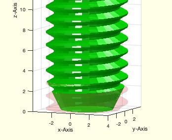
Many DIN and ISO standards for machine elements expect a point tip shape at the end of a screw. This SGtool can be used as negtive form for shaping a tip of a bolt or screw etc.
See Also: SGmagnetcap
, SGpinwrenchsize
, SGbladeofpincone
Example Illustration
Syntax
SGtoolTip(d1,d2,[w])
Input Parameter
d1: | | outer diameter |
d2: | | tip diameter |
w: | | optional angle; default is 90 degree |
Examples
SGA=SGtoolTip(8,5); SGfigure(SGA)
SGB=SGDIN13(8,20);
SGsubtract(SGB,SGA,'alignunder',+0.1)
Copyright 2015-2025 Tim C. Lueth. All rights reserved. The code is the property of Tim C. Lueth and may not be redistributed or modified without explicit written permission. This software may be used free of charge for academic research and teaching purposes only. Commercial use, redistribution, modification, or reverse engineering is strictly prohibited. Access to source code is restricted and granted only under specific agreements. For licensing inquiries or commercial use, please contact: Tim C. Lueth
Algorithm (Workflow)
This function, SGtoolTip, is designed to create a subtraction solid for shaping the tip of a bolt or screw, commonly used in machine elements according to DIN and ISO standards.
Input Parameters
- d1: Outer diameter of the tool.
- d2: Tip diameter of the tool.
- w: Optional angle, defaulting to 90 degrees if not provided.
Algorithm Steps
- Set the default angle
w to 90 degrees. If a third argument is provided and is not empty, update w with this value.
- Define a constant
t as 2.
- Calculate
n using the function nofrd(d1+t), which determines the number of facets or divisions based on the outer diameter plus t.
- Compute the height
h of the tool using the formula: h = tan((180-w)/2/180*pi) * (d1-d2). This calculates the height based on the angle and the difference between the outer and tip diameters.
- Create two circles using the function
PLcircle with radii d1/2 and d1/2+t, both divided into n segments.
- Concatenate the circle point lists into
CPL, separating them with NaN NaN to indicate a break between the two circles.
- Generate the polygon list
PL and edge list EL from the concatenated point list CPL using PLELofCPL.
- Create the solid geometry
SG from the concatenated point list CPL and height h using SGofCPLz.
- Adjust the vertices of the solid geometry
SG by scaling the x and y coordinates of the second set of vertices (from n+1 to 2n) by the ratio d2/d1.
- If no output is requested, display the parameters
d1, d2, h, and d1+t, and visualize the solid geometry using VLFLfigure.
Algorithm explaination created using ChatGPT on 2025-08-19 01:39. (Please note: No guarantee for the correctness of this explanation)
Last html export of this page out of FM database by TL: 2025-09-21