by Tim C. Lueth, SG-Lib Toolbox: SolidGeometry 5.6 - Completed CAD designs
Introduced first in SolidGeometry 5.0, Creation date: 2020-11-01, Last change: 2025-09-15
See Also: SGmakitaadapter
, SGveribor210
, SGveribor120yannick
SG=SGveribor120
SG: | Solid Geometry of a Veribor 120 |
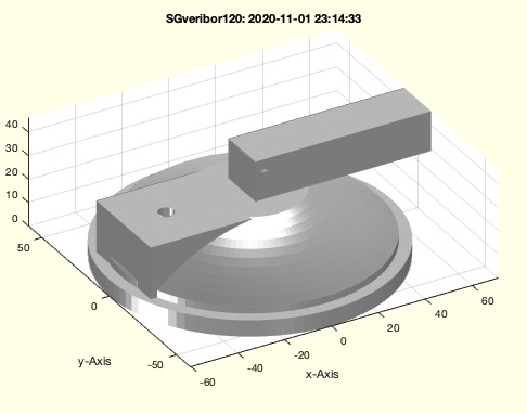
SGveribor120; SG=ans;This function, SGveribor120, generates the solid geometry of a Veribor 120 mm suction cup. The algorithm is structured to create and manipulate various geometric shapes to form the final model.
The function does not take any input parameters directly. It uses predefined values and functions to construct the geometry.
SG: Solid Geometry of a Veribor 120
ol = 0.01.A with a diameter of 120 mm and a height of 7 mm using SGofCPLz and PLcircle.B with a diameter of 110 mm and a height of 3 mm plus offset ol. Color its faces red using SGcolorfaces.B on top of A with a slight offset using SGtransrelSG and merge them with SGunion.C with a radius of 110 mm, width of 22 mm, and a 90-degree bend using SGofCPLrot and CPLcircbend.C on top of the combined shape A and merge using SGconcat.D with dimensions [43, 40.2, 22-ol] and transform it using SGofSGT.XX with a diameter of 6.5 mm and a height of 15 mm. Position it inside D and subtract it from D using SGsubtract.D with A and merge using SGunion. Cut A at a height of 29 mm using SGcut.E with dimensions [7, 7, 16+ol] and transform it using SGofSGT.E on top of A and merge using SGunion.H with dimensions [75, 20, 17] and transform it using SGofSGT.H with E and merge with A using SGconcat.R with a diameter of 2 mm and a height of 24 mm. Rotate it 90 degrees around the X-axis and position it relative to E.R with A using SGconcat.SG.SSS under C with a height of 40 mm using SGplateunder and SGofCPLrot.SSS slightly downwards using SGtransP.SG using SGTset and TofFS.SGfigure and SGTplotalpha.