exp_2018_08_17_ATMEGA256- SCRIPT for analyzing drilling holes in an STL printed circuit board based on image projection |
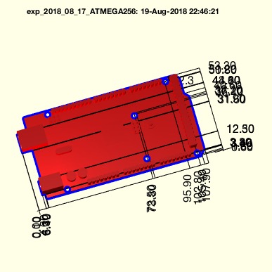 | % exp_2018_08_17_ATMEGA256 - SCRIPT for analyzing drilling holes in an STL printed circuit board based on image projection % (by Tim Lueth, VLFL-Lib, 2018-AUG-17 as class: EXPERIMENTS) % % Introduced first in SolidGeometry 4.3 % % exp_2018_08_17_ATMEGA256 % % % Copyright 2018 Tim C. Lueth |
symbforwkine(a,b,WL)- returns a forward kinematic calculation from a symbolics links list description |
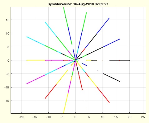 | % symbforwkine(a,b,WL) - returns a forward kinematic calculation from a symbolics links list description % (by Tim Lueth, VLFL-Lib, 2018-AUG-16 as class: EXPERIMENTS) % % This fnctn takes a cell list "b" of symbolic 4x4 matrices with exactly % one degree of freedom (1DoF). They are generated, for example, by the % fnctn SGTofDHset. % These are now converted by matrix multiplication into fnctns of the % endpoints of a kinematic chain. The first 4x4 matrix has 1Dof, the % second matrix then 2DoF etc. This cell list Ti of the symbolic % equations for calculating the endpoints of the kinematic chain is then % converted into a cell list H of handeles of the corresponding matlab % fnctns. The fnctns in H can then be used to calculate the endpoints % numerically. Optionally, an angle list is generated, which is a % permutation of angle positions at each DoF. (Status of: 2018-08-26) % % Introduced first in SolidGeometry 4.2 % % See also: SGTofDHset % % [Ti,LL,H]=symbforwkine(a,b,[WL]) % === INPUT PARAMETERS === % a: unused yet % b: cell list of n symbolics symbolic HT matrices x of 1doF rotational % links % WL: List of k angles of n links [k x l] % === OUTPUT RESULTS ====== % Ti: cell list of n symbolic HT matrices of b link end points % LL: matrix [n x 3 x k] % H: matlab fnctn handles the calculation of Ti % % EXAMPLE: % SGTofDHset([20 0 pi/2 0 ;0 10 pi 0;0 10 0 pi/2;10 0 pi/4 0; 10 0 pi/4 0]); show % [a,b]=SGTofDHset([20 0 pi/2 0 ;0 10 pi 0;0 10 0 pi/2;10 0 pi/4 0; 10 0 pi/4 0]); % symbforwkine(a,b); % [e,f,g]=symbforwkine(a,b,2) % e{:},g{:} % % See also: SGTofDHset % % % Copyright 2018 Tim C. Lueth |
exp_2018_08_14_forwkinsym(a,b,WL)- EXPERIMENT that returns a forward kinematic calculation from a symbolics links list description |
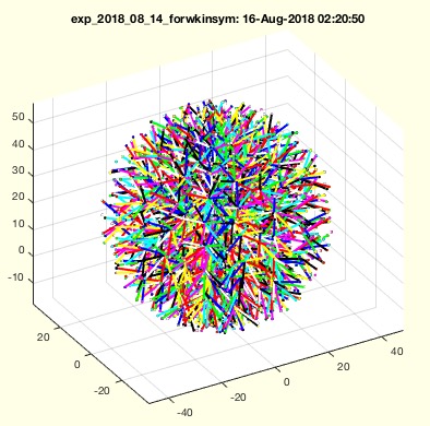 | % exp_2018_08_14_forwkinsym(a,b,WL) - EXPERIMENT that returns a forward kinematic calculation from a symbolics links list description % (by Tim Lueth, VLFL-Lib, 2018-AUG-14 as class: EXPERIMENTS) % % will be renamed into symbforwkine (Status of: 2018-08-20) % % Introduced first in SolidGeometry 4.2 % % [Ti,LL,H]=exp_2018_08_14_forwkinsym(a,b,[WL]) % === INPUT PARAMETERS === % a: unused yet % b: cell list of n symbolics symbolic HT matrices x of 1doF rotational % links % WL: List of k angles of n links [k x l] % === OUTPUT RESULTS ====== % Ti: cell list of n symbolic HT matrices of b link end points % LL: matrix [n x 3 x k] % H: matlab fnctn handles the calculation of Ti % % EXAMPLE: % SGTofDHset([20 0 pi/2 0 ;0 10 pi 0;0 10 0 pi/2;10 0 pi/4 0; 10 0 pi/4 0]); % [a,b]=SGTofDHset([20 0 pi/2 0 ;0 10 pi 0;0 10 0 pi/2;10 0 pi/4 0; 10 0 pi/4 0]); % exp_2018_08_14_forwkinsym(a,b); % [e,f,g]=exp_2018_08_14_forwkinsym(a,b,2) % e{:},g{:} % % % % Copyright 2018 Tim C. Lueth |
FLremdoublevertex(FL)- returns the indices of a FL that a double entry vertex index |
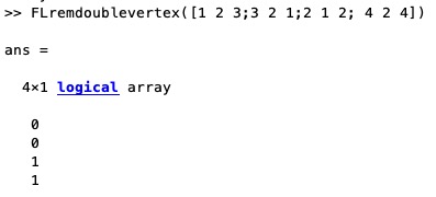 | % FLremdoublevertex(FL) - returns the indices of a FL that a double entry vertex index % (by Tim Lueth, VLFL-Lib, 2018-AUG-14 as class: AUXILIARY PROCEDURES) % % If in a Facet list there exist a degenerated traingle such as [1 1 2] % or [1 2 1] % this facet is found by this fnctn. % fi=FL(:,1)==FL(:,2) | FL(:,1)==FL(:,3) | FL(:,2)==FL(:,3); % (Status of: 2020-02-11) % % Introduced first in SolidGeometry 4.2 % % fi=FLremdoublevertex(FL) % === INPUT PARAMETERS === % FL: Facet list % === OUTPUT RESULTS ====== % fi: removal facet index % % EXAMPLE: % FLremdoublevertex([1 2 3;3 2 1;2 1 2; 4 2 4]) % % % Copyright 2018-2020 Tim C. Lueth |
SGofVLalphaShape(VL,al)- returns the alphashape of a vertex list |
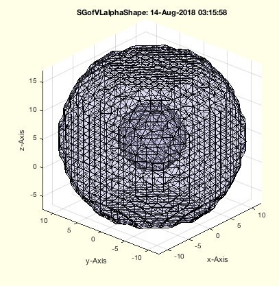 | % SGofVLalphaShape(VL,al) - returns the alphashape of a vertex list % (by Tim Lueth, VLFL-Lib, 2018-AUG-14 as class: TETRAHEDRONS) % % Introduced first in SolidGeometry 4.2 % % See also: alphaShape, alphaTriangulation, triangulation, freeBoundary % % SG=SGofVLalphaShape(VL,[al]) % === INPUT PARAMETERS === % VL: Vertex List % al: optional alpha radius % === OUTPUT RESULTS ====== % SG: Solid Geometry of the Alpha Shape % % EXAMPLE: % [a,b,c,d,e,f]=invkinrplan3(5,10,5); VL=f(e,:); SGfigure; VLplot(VL,'.'); view(-30,30) % SGofVLalphaShape(VL) % % See also: alphaShape, alphaTriangulation, triangulation, freeBoundary % % % Copyright 2018 Tim C. Lueth |
isrealr(VL)- returns whether all elements on a row are real |
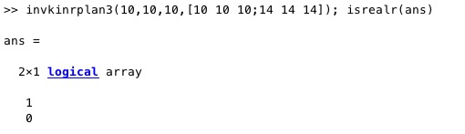 | % isrealr(VL) - returns whether all elements on a row are real % (by Tim Lueth, VLFL-Lib, 2018-AUG-14 as class: ANALYTICAL GEOMETRY) % % similar concept to norm and normc and normr (Status of: 2018-08-20) % % Introduced first in SolidGeometry 4.2 % % See also: isreal % % ri=isrealr(VL) % === INPUT PARAMETERS === % VL: vector list with rows and columns [n x m] % === OUTPUT RESULTS ====== % ri: index list; r(i)==true if all elements of VL(i,:) = real % % EXAMPLE: % invkinrplan3(10,10,10,[10 10 10;14 14 10]); isrealr(ans) % invkinrplan3(10,10,10,[10 10 10;14 14 14]); isrealr(ans) % % See also: isreal % % % Copyright 2018 Tim C. Lueth |
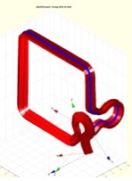
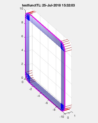
exp_2018_08_12_torsion (VL,wr,ccw,CPL,n)- EXPERIMENT to create torsion ropes |
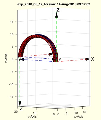 | % exp_2018_08_12_torsion (VL,wr,ccw,CPL,n) - EXPERIMENT to create torsion ropes % (by Tim Lueth, VLFL-Lib, 2018-AUG-13 as class: EXPERIMENTS) % % Several fnctns have already been designed by the author to extrude a % body along a path: SGofCPLCVVLR, SGcontourtube, SGcontourtube2, % SGofCPLtransT. If the cross-sectional contour CPL is always to be % perpendicular to the path and a rotation about the z-axis is to be % realized at the same time (torsion), the body is constricted. This can % only be avoided by deviating from the original path and placing a helix % around the path. This extends the distance and reduces constriction. % The rotation around ez is connected with a curvature around ex/ey. This % happens, for example, when shooting up a sheet while sailing or a % climbing rope. The inverse kinematics of a 6D robot also allows this % problem to be solved. % This experiment illustrates different couplings of a curvature with the % rotation around the z-axis. (Status of: 2018-08-20) % % Introduced first in SolidGeometry 4.2 % % exp_2018_08_12_torsion([VL,wr,ccw,CPL,n]) % === INPUT PARAMETERS === % VL: 2 Points as list {x1 y1 z1; x2 y2 z2] % wr: rotation angle % ccw: [fx fy fz] value for cw or ccw for rotation x rotation y and % rotation z; default is [1 1 1] % CPL: cross section contour ; default is CPLSample(33) % n: number of rotations per pi % % EXAMPLE: % testfunctTL('exp_2018_08_12_torsion('''',#3,[#1 #2]);',[-1 0 +1],[-1 0 +1],1*[pi -pi]) % % % Copyright 2018 Tim C. Lueth |
SGofCPLtransT(CPL,T1,T2)- returns a solid from a 2D contour and a list of frames |
 | % SGofCPLtransT(CPL,T1,T2) - returns a solid from a 2D contour and a list of frames % (by Tim Lueth, VLFL-Lib, 2018-AUG-13 as class: SURFACES) % % In combination with TLofCVL, this fnctn will replace in future mostly % all other fnctns such as: SGofCPLCVLR, SGcontourtube, SGcontourtube2, % SGof2T, SGof2SGT. (Status of: 2018-08-20) % % Introduced first in SolidGeometry 4.2 % % See also: TLofCVL, SGofCPLCVLR, SGcontourtube, SGcontourtube2, SGof2T, % SGof2SGT % % [SG,FLS,FLE,FLW,TS,TE]=SGofCPLtransT(CPL,T1,[T2]) % === INPUT PARAMETERS === % CPL: Closed Polygon List separated by nan % T1: Frame 1 [4 x 4] or List of frames [4 x 4 x n] % T2: Frame 2 [4 x 4], optional % === OUTPUT RESULTS ====== % SG: Solid Geometry SG.VL, SG.FL % FLS: Facets of the start cover % FLE: Facets of the end cover % FLW: Facets of the contour wall % TS: starting frame % TE: ending frame % % EXAMPLE: % SGofCPLtransT(CPLsample(13),eye(4),TofR(rot(0,0,pi/20),[0 0 40])); % TL=TLofCVL(VLsample(4),2,eye(3),rot(0,0,pi/2),'rad'); SG=SGofCPLtransT(CPLsample(27)/20,TL); SGfigure(SG); view(-30,30); % % See also: TLofCVL, SGofCPLCVLR, SGcontourtube, SGcontourtube2, SGof2T, % SGof2SGT % % % Copyright 2018 Tim C. Lueth |
TLofCVL(OVL,R,T1,T2,typ,tor,aux)- returns a list of frames that connect a start frame and an end frame along a spatial contour |
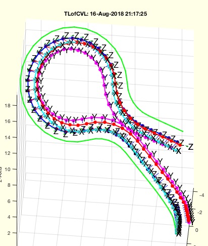 | % TLofCVL(OVL,R,T1,T2,typ,tor,aux) - returns a list of frames that connect a start frame and an end frame along a spatial contour % (by Tim Lueth, VLFL-Lib, 2018-AUG-11 as class: ANALYTICAL GEOMETRY) % % This fnctn creates a list of HT frames for a vertex list, a start frame % and an end frame as well as a radius specification with which a % transition between start and end frames can be achieved. First, % VLradialEdges2T adds radii to the contour in order to avoid strong % curvature changes. The rotation by ez remains between the Start Frame % and the End Frame. For this purpose support points are inserted on long % straight lines. Then the necessary rotation error between the start % frame and the end frame is determined in relation to the broken curve % surface normal (VLedgeNormal). The required rotatation is equally % distributed between start and end points (Status of: 2021-02-28) % % Introduced first in SolidGeometry 4.2 % % See also: SGofCPLtransT, VLradialEdges2T, VLedgeNormal % % Ti=TLofCVL([OVL,R,T1,T2,typ,tor,aux]) % === INPUT PARAMETERS === % OVL: Open Path to follow in 3D % R: Radius; default is 2 % T1: Start Frame % T2: End Frame % typ: type 'rad', 'rmax', 'tan'; default is 'rad'; see VLradialEdges2T % tor: true=>torsion; false=>no torsion; default is true % aux: distance of axiliary points; default is R/3 % === OUTPUT RESULTS ====== % Ti: List of HT-Matrixes (4 x 4 x n] for n vertices % % EXAMPLE: % TLofCVL(VLsample(7),2,eye(3),rot(0,0,pi/2),'rad');TL=ans; % TLofCVL(VLsample(7),2,eye(3),rot(0,0,pi/2),'rmax');TL=ans; % TLofCVL(VLsample(7),2,eye(3),rot(0,0,pi/2),'tan');TL=ans; % TLofCVL(VLsample(3),2,eye(3),rot(0,0,pi/2),'tan',true);TL=ans; % TLofCVL(VLsample(3),2,eye(3),rot(0,0,pi/2),'tan',false);TL=ans; % TLofCVL(VLsample(3),2,eye(3),rot(0,0,pi/2),'tan',false,inf);TL=ans; % No auxiliary points % TLofCVL(VLsample(3),2,eye(3),rot(0,0,pi/2),'tan',false,inf);TL=ans; % No radial solution points % % See also: SGofCPLtransT, VLradialEdges2T, VLedgeNormal % % % Copyright 2018-2021 Tim C. Lueth |
PLtangentcirc3(PL,R,maxR)- returns the a circ segment between p1 and p3 with radius R |
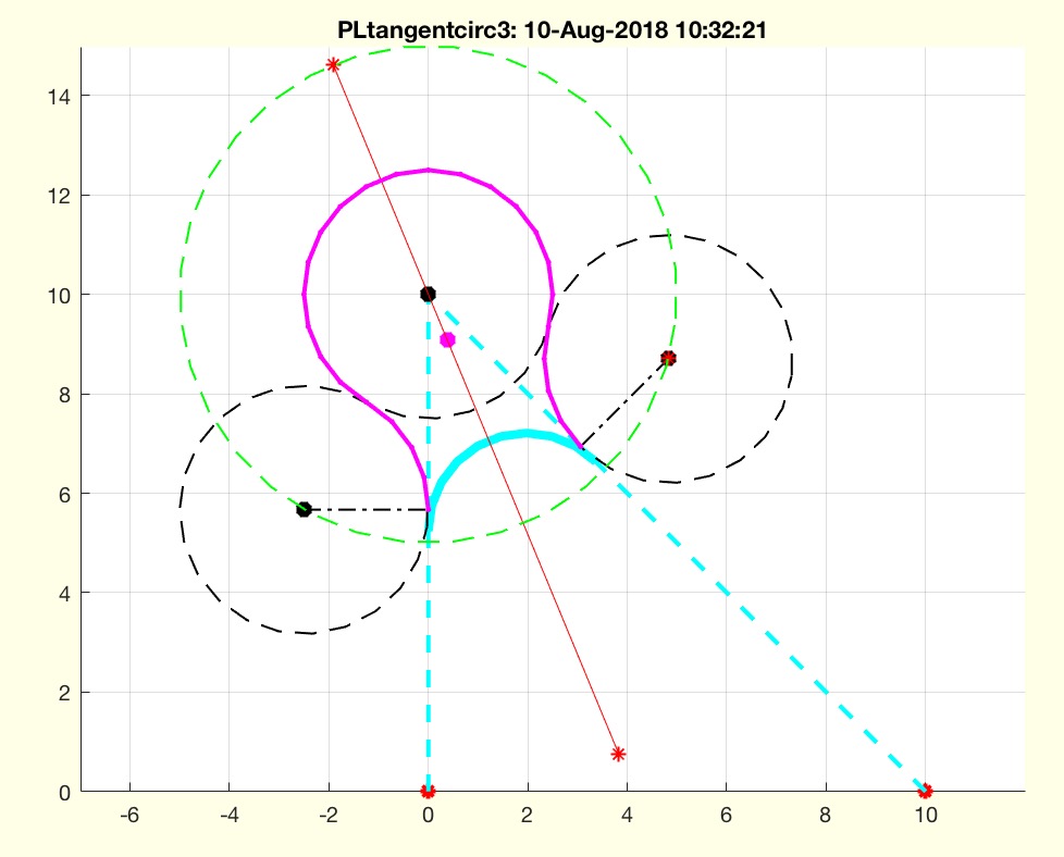 | % PLtangentcirc3(PL,R,maxR) - returns the a circ segment between p1 and p3 with radius R % (by Tim Lueth, VLFL-Lib, 2018-AUG-10 as class: ANALYTICAL GEOMETRY) % % A warning of thrown if the fnctn is called without R as 3rd output % argument in contrast to PLtangentcirc, this fnctn calculates an outer % radius solution instead of throwing a warning (Status of: 2018-08-10) % % Introduced first in SolidGeometry 4.2 % % See also: VLradialEdges, VLtangentcirc, PLtangentcirc, PLradialEdges, % VLradialEdges2T % % [PLE,p2x,R]=PLtangentcirc3([PL,R,maxR]) % === INPUT PARAMETERS === % PL: three points [p1; p2; p3] % R: Desired Radius % maxR: option to maximize the radius % === OUTPUT RESULTS ====== % PLE: Point List to replace 2nd point of the list % p2x: Center Points of the Radius % R: Radius used in PLtangentcirc % % EXAMPLE: try different examples % PLtangentcirc (CPLsample(1),5); % PLtangentcirc (PLsample(5)); % warning % [~,~,r]=PLtangentcirc (PLsample(5)) % No warning % % See also: VLradialEdges, VLtangentcirc, PLtangentcirc, PLradialEdges, % VLradialEdges2T % % % Copyright 2018 Tim C. Lueth |
sphere_line_intersection(l1,l2,sp,r)- returns the crossing points of a sphere and a straight line |
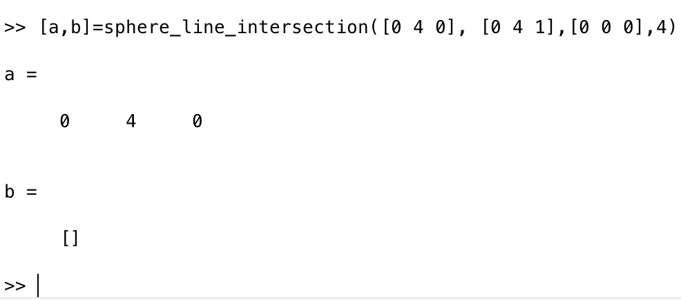 | % sphere_line_intersection(l1,l2,sp,r) - returns the crossing points of a sphere and a straight line % (by Paul Bourke & Campbell Barton, VLFL-Lib, 2018-AUG-08 as class: % ANALYTICAL GEOMETRY) % % This implementation is taken from the python 3.2 code: % http://paulbourke.net/geometry/circlesphere/ % http://paulbourke.net/geometry/circlesphere/sphere_line_intersection.py % and transfered to Matlab by Tim Lueth % at Greg Hager's House in Mt. Crested Butte (Status of: 2018-08-08) % % See also: crosscircline % % [p1,p2]=sphere_line_intersection(l1,l2,sp,r) % === INPUT PARAMETERS === % l1: line point 1 [ x y z] % l2: line point 2 [ x y z] % sp: sphere center coordinate [ x y z] % r: radius R % === OUTPUT RESULTS ====== % p1: return crossing point 1 if exist or [] % p2: return crossing point 2 if exist or [] % % EXAMPLE: % [a,b]=sphere_line_intersection([0 0 0], [0 0 1],[0 0 0],4) % two % crossing points % [a,b]=sphere_line_intersection([0 4 0], [0 4 1],[0 0 0],4) % one % crossing point % % See also: crosscircline % |
crosscircline(C,R,p,ez)- returns the cross points of a circle and a straight line |
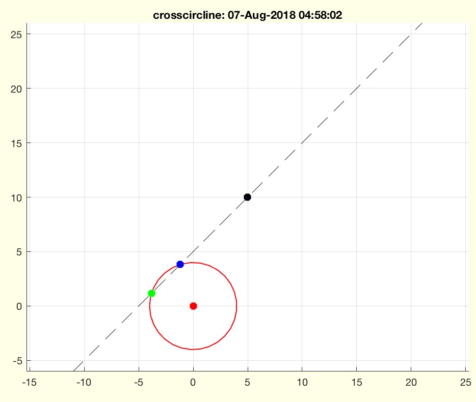 | % crosscircline(C,R,p,ez) - returns the cross points of a circle and a straight line % (by Tim Lueth, Video-Lib, 2018-AUG-06 as class: ANALYTICAL GEOMETRY) % % The solution was created using the Symbolics toolbox. Therefor, the % solutions may not correspond. % syms cx cy w R y0 k y1 x0 k x1 % r=solve(cx + cos (w) * R ==y0 + k * y1, cy +sin (w) * R == x0 + k * % x1,k,w,'Real',true) % (Status of: 2018-08-08) % % Introduced first in SolidGeometry 4.2 % % See also: tangent2circ, circcirc, cross2circ, PLof3dist, PLchordof2PR, % crossz, PLcross2Lines % % [P,K,W]=crosscircline(C,R,p,ez) % === INPUT PARAMETERS === % C: Center of circle [x y] % R: Radius of circle % p: point on straight line % ez: direction of straight line % === OUTPUT RESULTS ====== % P: List of 2 Points % K: List of 2 K values % W: List of two angle % % EXAMPLE: % testfunctTL('crosscircline([0 0],4,[#1 #2],[.5 1])',[-5 5],[-3 2]); % testfunctTL('crosscircline([0 0],6,[#1 #2],[.5 1])',[-5 5],[-3 2]); % crosscircline([0 0],4,[0 2],[1 1]) % two solutions % crosscircline([0 0],4,[5 5],[1 1]) % two solutions % crosscircline([0 0],4,[4 10],[0 1]) % one Solution % crosscircline([0 0],4,[5 10],[0 1]) % No Solution % % See also: tangent2circ, circcirc, cross2circ, PLof3dist, PLchordof2PR, % crossz, PLcross2Lines % % % Copyright 2018 Tim C. Lueth |
exp_2018_08_04_jointsubstraction- EXPERIMENT TO CREATE A SUBSTRACTION BODY FOR CREATING JOINTS FROM BARS |
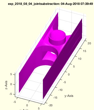 | % exp_2018_08_04_jointsubstraction - EXPERIMENT TO CREATE A SUBSTRACTION BODY FOR CREATING JOINTS FROM BARS % (by Tim Lueth, VLFL-Lib, 2018-AUG-04 as class: EXPERIMENTS) % % Just before flying out to Prof. Greg Hager (JHU) in Colorado (Status % of: 2020-07-03) % % Introduced first in SolidGeometry 4.2 % % See also: exp_2020_07_02_subtractjoint % % F=exp_2018_08_04_jointsubstraction % === OUTPUT RESULTS ====== % F: Final Substraction Body % % See also: exp_2020_07_02_subtractjoint % % % Copyright 2018-2020 Tim C. Lueth |
SGsimpleNDItracker(d,H,A)- creates a tracker for NDI spheres using a distance list |
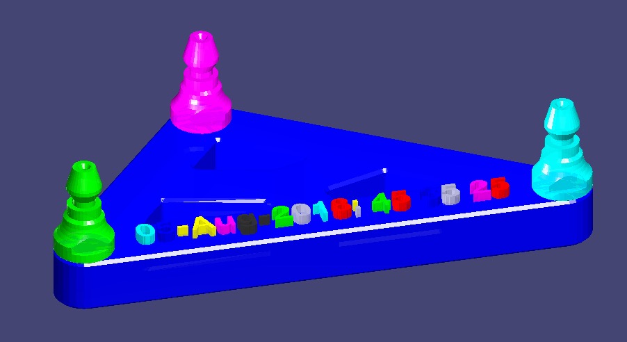 | % SGsimpleNDItracker(d,H,A) - creates a tracker for NDI spheres using a distance list % (by Tim Lueth, VLFL-Lib, 2018-AUG-01 as class: MODELING PROCEDURES) % % Introduced first in SolidGeometry 4.2 % % See also: SGsimpleHinge % % [SG,cp]=SGsimpleNDItracker(d,[H,A]) % === INPUT PARAMETERS === % d: distance list such as [40 50 60] % H: height of the tracker % A: Geometry of the mounting posts % === OUTPUT RESULTS ====== % SG: Resulting Solid Geoemtry % cp: center point % % EXAMPLE: % loadweb NDI_STLs.mat % SGsimpleNDItracker([80 50 40],'',NDI_mountingpost); % A=SGsimpleNDItracker([80 50 40],[],NDI_mountingpost); % B=SGbending(A,40); SGfigure(B) % % See also: SGsimpleHinge % % % Copyright 2018 Tim C. Lueth |
PLchordof2PR(PL,R,rhand)- returns a radial segment for a given chord / arc tendon and a radius |
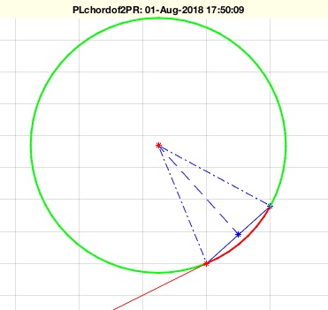 | % PLchordof2PR(PL,R,rhand) - returns a radial segment for a given chord / arc tendon and a radius % (by Tim Lueth, VLFL-Lib, 2018-AUG-01 as class: ANALYTICAL GEOMETRY) % % Introduced first in SolidGeometry 4.2 % % See also: tangent2circ, circcirc, cross2circ, crosscircline, PLof3dist, % crossz, PLcross2Lines, sofrd, dofRintrusion, rofRintrusion, % Rofrdintrusion % % [PL1,PL2,m1,m2]=PLchordof2PR(PL,R,[rhand]) % === INPUT PARAMETERS === % PL: [starting point of chord; end point of chord] % R: Radius % rhand: true = right hand; false = left hand; default is true % === OUTPUT RESULTS ====== % PL1: short angle (red) % PL2: long angle (green) % m1: center on left side % m2: center on right side % % EXAMPLE: % PLchordof2PR([0 0;10 0],5) % PLchordof2PR([0 0;10 0],9) % PLchordof2PR([0 0; 10 9],20,false); % PLchordof2PR([0 0; 10 9],20,true); % % See also: tangent2circ, circcirc, cross2circ, crosscircline, PLof3dist, % crossz, PLcross2Lines, sofrd, dofRintrusion, rofRintrusion, % Rofrdintrusion % % % Copyright 2018-2021 Tim C. Lueth |
SGboxpacking(SG,tstr,dim,turn)- combines SGpacking and SGboxing |
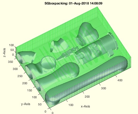 | % SGboxpacking(SG,tstr,dim,turn) - combines SGpacking and SGboxing % (by Tim Lueth, VLFL-Lib, 2018-AUG-01 as class: AUXILIARY PROCEDURES) % % Auxiliaray fnctn to prepare print jobs for Selective Laser Sintering % (Status of: 2018-08-01) % % Introduced first in SolidGeometry 4.2 % % See also: SGpacking, SGboxing, SGpatternXYZ, SGcopyrotZ, SGarrangeSG, % SGarrangeSGC, SGCaddSGn, SGCaddSG % % [SGC,SGA,SGB]=SGboxpacking(SG,[tstr,dim,turn]) % === INPUT PARAMETERS === % SG: SG or SGcs to pack and box % tstr: text string for cover % dim: Box dimensions for printing % turn: false==keep orientation; true==optimize space; default is true % === OUTPUT RESULTS ====== % SGC: complete print job SG % SGA: packaged solids of SG % SGB: box aroound SGA % % EXAMPLE: % loadweb JACO_robot.mat; SGboxpacking(JACO,'JACO-ROBOT',[500 500 500]); % SGboxpacking(JACO,'JACO-ROBOT',[500 500 500],false); % % % See also: SGpacking, SGboxing, SGpatternXYZ, SGcopyrotZ, SGarrangeSG, % SGarrangeSGC, SGCaddSGn, SGCaddSG % % % Copyright 2018 Tim C. Lueth |
SGofVLFLSGc(SGc)- returns only the Solid Geometry of structs, Solid, Vertex or Facet list |
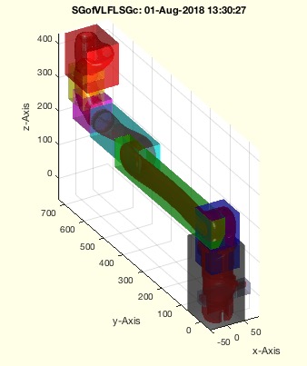 | % SGofVLFLSGc(SGc) - returns only the Solid Geometry of structs, Solid, Vertex or Facet list % (by Tim Lueth, VLFL-Lib, 2018-AUG-01 as class: SURFACES) % % all frames etc are lost. This fnctn is used to structure several % printjobs % Could be extended to handels, pde models etc. (Status of: 2018-08-01) % % Introduced first in SolidGeometry 4.2 % % See also: SGpacking % % SG=SGofVLFLSGc(SGc) % === INPUT PARAMETERS === % SGc: Any kind of SG: A.SG, A{}, A.VL,A.FL % === OUTPUT RESULTS ====== % SG: Struct only with fields SG.Vl and SG.FL % % EXAMPLE: % load JACO_robot.mat % SGofVLFLSGc(JACO) % % % See also: SGpacking % % % Copyright 2018 Tim C. Lueth |
PLtransC(PL,C,w)- rotates a point list around a center |
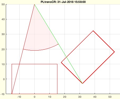 | % PLtransC(PL,C,w) - rotates a point list around a center % (by Tim Lueth, VLFL-Lib, 2018-JUL-31 as class: CLOSED POLYGON LISTS) % % Introduced first in SolidGeometry 4.2 % % See also: PLtransP, PLtransR, PLtrans, PLtrans0, PLtrans1, PLtransT % % PL=PLtransC(PL,C,w) % === INPUT PARAMETERS === % PL: Point List [nx2] % C: Center of rotation default is zero % w: angle of rotation default is pi/2 % === OUTPUT RESULTS ====== % PL: Resulting Point list % % EXAMPLE: % PLtransC(PLsquare(30,20),[0 50],pi/4) % % See also: PLtransP, PLtransR, PLtrans, PLtrans0, PLtrans1, PLtransT % % % Copyright 2018 Tim C. Lueth |
SGsimpleHinge(H,D,X,sl,ch,oa,ba,Ri);- returns a simple swivel hinge |
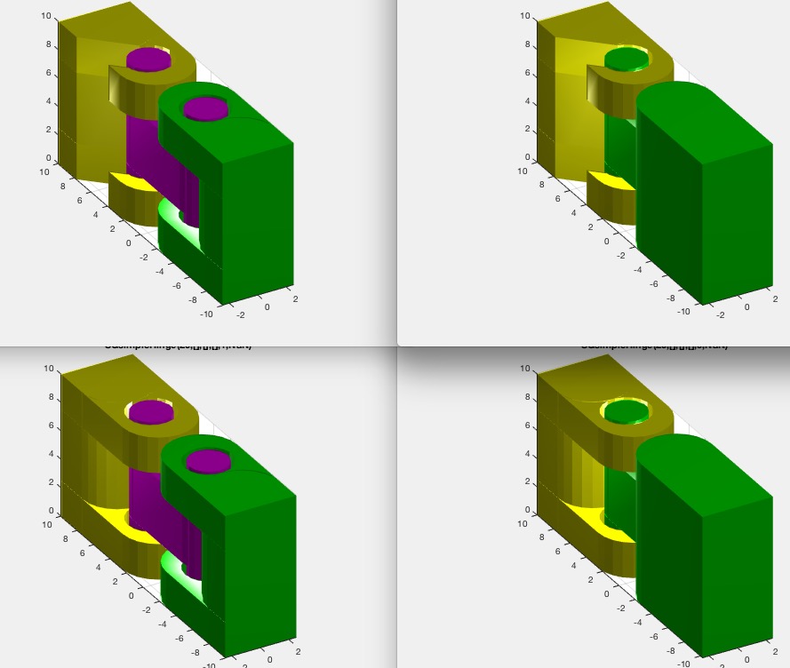 | % SGsimpleHinge(H,D,X,sl,ch,oa,ba,Ri); - returns a simple swivel hinge % (by Tim Lueth, VLFL-Lib, 2018-JUL-30 as class: MODELING PROCEDURES) % % First version as tutorial for Alexandra Mercader (Status of: 2018-08-01) % % Introduced first in SolidGeometry 4.2 % % See also: SGmodelLink2 % % [SG,SG1,SG2,SG3]=SGsimpleHinge([H,D,X,sl,ch,oa,ba,Ri]); % === INPUT PARAMETERS === % H: height in z % D: depth in y; default is H/2 % X: Depth in x; default is D/2 % sl: slot size; default is 0.3mm for SLS % ch: chain; default is false % oa: opening angle starting at 5*pi/4; default is []==closed % ba: angle intervall [intervall, start]; not supported yet % Ri: inner Radius; default is R/1.5 % === OUTPUT RESULTS ====== % SG: Complete Solid Geometry % SG1: Upper Part, 'yellow % SG2: Lower Part % SG3: Middle Part % % EXAMPLE: % SGsimpleHinge(20,20,5); SGanalyzeGroupParts(ans) % SGsimpleHinge(20,20,5,'',true); SGanalyzeGroupParts(ans) % SGsimpleHinge(20,20,5,'',true,0); SGanalyzeGroupParts(ans) % testfunctTL('SGsimpleHinge(20,[],[],[],#1,#2)',[true,false],[nan 0]) % % See also: SGmodelLink2 % % % Copyright 2018 Tim C. Lueth |
tangent2circ(A0,B0,ra,rb)- returns outer and inner tangents of 2 circles |
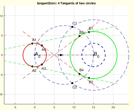 | % tangent2circ(A0,B0,ra,rb) - returns outer and inner tangents of 2 circles % (by Tim Lueth, VLFL-Lib, 2018-JUL-29 as class: ANALYTICAL GEOMETRY) % % The angle can be used such as A1=A0+[ex*cos(+w1)+ey*sin(+w1)]*ra; % (Status of: 2018-08-02) % % Introduced first in SolidGeometry 4.2 % % See also: cross2circ, PLof3dist, PLchordof2PR, crossz % % [A,B,exey,w]=tangent2circ(A0,B0,ra,rb) % === INPUT PARAMETERS === % A0: Center of circle A % B0: Center of circle B % ra: radius of circle A % rb: radius of circle B % === OUTPUT RESULTS ====== % A: Positions outer 1 outer 2 inner 1 inner 2 of circle A [4 x 2] % B: Positions outer 1 outer 2 inner 1 inner 2 of circle B [4 x 2] % exey: [ex;ey vector starting at A0 towards B0 % w: angle solutions relative to ex and ey % % EXAMPLE: try % tangent2circ([0 0],[15 0],3,6) % 4 Solutions % tangent2circ([0 0],[10 0],6,6) % 2 Solutions % tangent2circ([0 0],[2 0],6,3) % 0 Solutions % % tangent2circ([0 0],[4 0],4,2) % 2 Solutions % tangent2circ([0 0],[4 0],2,2) % 2 Solutions touching circle % tangent2circ([0 0],[4 0],1,6) % No Solution % % See also: cross2circ, PLof3dist, PLchordof2PR, crossz % % % Copyright 2018 Tim C. Lueth |
VLradialEdges2T(VL,R,TA,TB)- returns a vertex list (VL) with rounded/broken wrt to start and end frames |
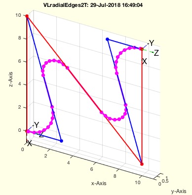 | % VLradialEdges2T(VL,R,TA,TB) - returns a vertex list (VL) with rounded/broken wrt to start and end frames % (by Tim Lueth, VLFL-Lib, 2018-JUL-29 as class: ANALYZING PROCEDURES) % % VLradialEdges uses VLtangentcirc uses PLtangentcirc % Replaces edges by a radial curve. The desired radius can be reduced % automatically if necessary. It is possible to maximize the radius % automatically. % In case that R is negative; VLbreakEdges is used instead (Status of: % 2018-07-29) % % Introduced first in SolidGeometry 4.2 % % See also: PLradialEdges, SGcontourtube, RLofEulerInterpolation, % VLinsertEulerSteps, VLradialEdges, TofPez, PLtangentcirc, % VLtangentcirc, SGbreakCorners, SGradialCorners % % NVL=VLradialEdges2T(VL,[R,TA,TB]) % === INPUT PARAMETERS === % VL: Vertex list nx3 % R: Radius; default is 1 % TA: Rotation Matrix for Start Point % TB: Rotation Matrix for End Point % === OUTPUT RESULTS ====== % NVL: New vertex list % % EXAMPLE: % VLradialEdges2T(VLsample(5),+3,TofR(rot(0,pi/2,0)),rot(0,pi/1.2,0)) % VLradialEdges2T(VLsample(5),-3,TofR(rot(0,pi/2,0)),rot(0,pi/1.2,0)) % % See also: PLradialEdges, SGcontourtube, RLofEulerInterpolation, % VLinsertEulerSteps, VLradialEdges, TofPez, PLtangentcirc, % VLtangentcirc, SGbreakCorners, SGradialCorners % % % Copyright 2018 Tim C. Lueth |
PLtransform_2018(PLA,PLB,sl,CL)- transforms ONE PL into another PL |
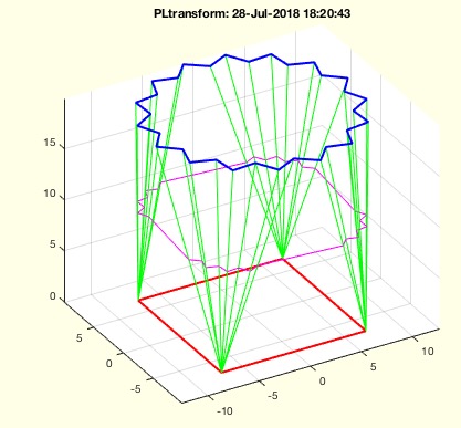 | % PLtransform_2018(PLA,PLB,sl,CL) - transforms ONE PL into another PL % (by Tim Lueth, VLFL-Lib, 2018-JUL-28 as class: CLOSED POLYGON LISTS) % % PLtransform returns OPEN CPLs % Make sure that orientation is the same (Status of: 2020-08-27) % % Introduced first in SolidGeometry 4.2 % % See also: SGof2CPLz, FLofPLcorrelation, PLcorrelate, CPLcorrelate, % PLtransform % % PLc=PLtransform_2018(PLA,PLB,[sl,CL]) % === INPUT PARAMETERS === % PLA: Point list A % PLB: Point list B % sl: percentage between 0==PLA and 1==PLB; list of values % CL: Correlation List, see PLcorrelate % === OUTPUT RESULTS ====== % PLc: CPL ==> or cell list of CPLs if numel (sl)>1 % % EXAMPLE: % PLtransform(CPLofPL(PLcircle(10,4)),CPLofPL(PLstar(10)),0.5) % PLtransform(CPLofPL(PLstar(10)),CPLofPL(PLcircle(10,4)),0.2) % PLtransform(CPLofPL(PLstar(10)),CPLofPL(PLcircle(10,4)),0.5); PLc=ans % PLtransform(CPLofPL(PLstar(10)),CPLofPL(PLcircle(10,4)),[0.5 0.7]); PLc=ans % % % See also: SGof2CPLz, FLofPLcorrelation, PLcorrelate, CPLcorrelate, % PLtransform % % % Copyright 2018-2021 Tim C. Lueth |
Tsample- shows samples of frames based on Tofn |
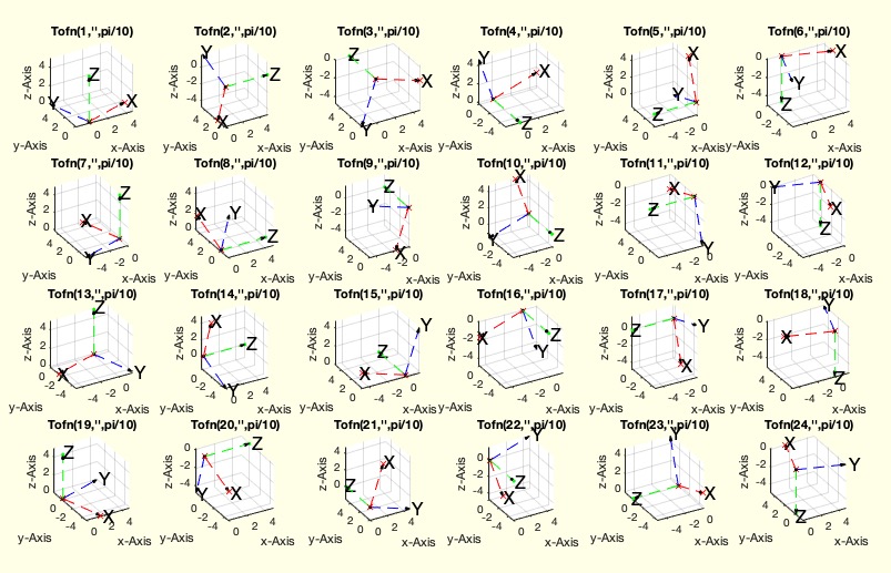 | % Tsample - shows samples of frames based on Tofn % (by Tim Lueth, VLFL-Lib, 2018-JUL-28 as class: KINEMATICS AND FRAMES) % % rewritten completely based on Tofn in SG-Lib 5.2 (Status of: 2022-04-02) % % Introduced first in SolidGeometry 4.2 % % See also: Tofn, TLofn % % Tsample % % See also: Tofn, TLofn % % % Copyright 2018-2022 Tim C. Lueth |
DeepL- just opens the browser with the DeepL translation tool |
 | % DeepL - just opens the browser with the DeepL translation tool % (by Tim Lueth, VLFL-Lib, 2018-JUL-28 as class: AUXILIARY PROCEDURES) % % Introduced first in SolidGeometry 4.2 % % See also: SGgrabcad % % DeepL % % EXAMPLE: Just try: DeepL % % See also: SGgrabcad % % % Copyright 2018 Tim C. Lueth |
SGTbaseunderSG(SGR)- creates a solid as base plated under a given solid |
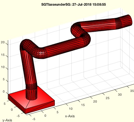 | % SGTbaseunderSG(SGR) - creates a solid as base plated under a given solid % (by Tim Lueth, VLFL-Lib, 2018-JUL-27 as class: KINEMATICS AND FRAMES) % % Introduced first in SolidGeometry 4.2 % % See also: SGplateunder % % [SG,SGC]=SGTbaseunderSG(SGR) % === INPUT PARAMETERS === % SGR: Solid or Cell list of SOlids % === OUTPUT RESULTS ====== % SG: Solid under the first Element of SG % SGC: Cell list with SG as now first element % % EXAMPLE: % SGTofDHset([20 0 pi/2 0;0 20 pi 0; 0 20 0 pi/2]); A=ans % SGTbaseunderSG(A); % % See also: SGplateunder % % % Copyright 2018 Tim C. Lueth |
permutevector(ps1,ps2,ps3)- creates vector list based on parametersets |
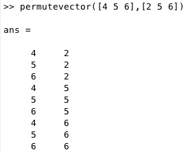 | % permutevector(ps1,ps2,ps3) - creates vector list based on parametersets % (by Tim Lueth, VLFL-Lib, 2018-JUL-26 as class: AUXILIARY PROCEDURES) % % Introduced first in SolidGeometry 4.2 % % See also: publishTL, testfunctTL % % VL=permutevector([ps1,ps2,ps3]) % === INPUT PARAMETERS === % ps1: paraneter set 1 % ps2: paraneter set 2 % ps3: paraneter set 3 % === OUTPUT RESULTS ====== % VL: Value vector list % % EXAMPLE: % permutevector([4 5 6],[2 5 6],[9 8]) % permutevector([4 5 6],[2 5 6]) % permutevector([4 5 6]) % % See also: publishTL, testfunctTL % % % Copyright 2018 Tim C. Lueth |
forwkinrplan3(d1,a2,a3,WL)- forward kinematic of a planar rz 2 arm rotating around an arm z axis |
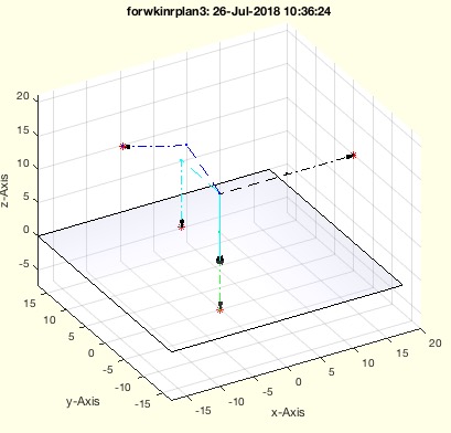 | % forwkinrplan3(d1,a2,a3,WL) - forward kinematic of a planar rz 2 arm rotating around an arm z axis % (by Tim Lueth, VLFL-Lib, 2018-JUL-26 as class: KINEMATICS AND FRAMES) % % Introduced first in SolidGeometry 4.2 % % See also: invkinrplan3, SGTofDHset, SGTofDenavitHartenberg % % [VL3,VL2,VL1,RL3,TL3]=forwkinrplan3(d1,a2,a3,[WL]) % === INPUT PARAMETERS === % d1: distance of link 1 % a2: width of link 2 % a3: width of link 3 % WL: Linst of angle (n x 3) % === OUTPUT RESULTS ====== % VL3: Coordinates of link3 % VL2: Coordinates of link2 % VL1: Coordinates of link1 % RL3: Rotation matrix at link 3 [3,3,n] % TL3: HT matrix at link 3 [4,4,n] % % EXAMPLE: % forwkinrplan3(10,10,10,[0 0 0; pi pi/3 pi/4;pi/3 -pi/3 pi/3; pi/2 0 % pi/2 ]) % % See also: invkinrplan3, SGTofDHset, SGTofDenavitHartenberg % % % Copyright 2018 Tim C. Lueth |
invkinrplan3(d1,a2,a3,VL)- returns the angles for a rotating planar two arm kinematic |
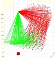 | % invkinrplan3(d1,a2,a3,VL) - returns the angles for a rotating planar two arm kinematic % (by Tim Lueth, VLFL-Lib, 2018-JUL-26 as class: KINEMATICS AND FRAMES) % % This fnctn contains the solution for a Jaco-Style 3DoF Kinematic % (Status of: 2018-07-27) % % Introduced first in SolidGeometry 4.2 % % See also: forwkinrplan3, invkinplan2 % % [aW,aU,bW,bU,ri,VL]=invkinrplan3(d1,a2,a3,[VL]) % === INPUT PARAMETERS === % d1: Height of the base % a2: length of link 2 % a3: length of link 3 % VL: Vertex list [n x 3] % === OUTPUT RESULTS ====== % aW: Set of Configuration A (ellbow up) % aU: Set of Configuration B (ellbow down) % bW: Set of Configuration C (reverse ellbow up) % bU: Set of Configuration D (reverse (ellbow down) % ri: row index of VL for real solutions % VL: Vertex list if created by this fnctn % % EXAMPLE: % invkinrplan3(20,15,10,permutevector(2:2:10,2:2:10,0)); % % See also: forwkinrplan3, invkinplan2 % % % Copyright 2018 Tim C. Lueth |
subfig (p)- creates subfigures on the screen similar to subplot |
 | % subfig (p) - creates subfigures on the screen similar to subplot % (by Tim Lueth, VLFL-Lib, 2018-JUL-25 as class: VISUALIZATION) % % Introduced first in SolidGeometry 4.2 % % See also: copyfig % % subfig([p]) % === INPUT PARAMETERS === % p: position similar to subplot % % EXAMPLE: % for i=1:4; SGfigure(SGbox([30,20,10])); view(-30,30);end % for i=1:4; SGfigure(SGbox([30,20,10])); view(-30,30); copyfig; end % for i=1:4; SGfigure(SGbox([30,20,10])); view(-30,30); copyfig; % subfig(i); end % % See also: copyfig % % % Copyright 2018 Tim C. Lueth |
testfunctTL(Eterm,)- testing macro that executes creates a list of different parametertests |
 | % testfunctTL(Eterm,) - testing macro that executes creates a list of different parametertests % (by Tim Lueth, VLFL-Lib, 2018-JUL-25 as class: AUXILIARY PROCEDURES) % % uses evalin('caller',eterm) for execution to be able to use the defined % variables in the command workspace (Status of: 2018-07-28) % % Introduced first in SolidGeometry 4.2 % % See also: publishTL, permutevector % % testfunctTL(Eterm,[]) % === INPUT PARAMETERS === % Eterm: fnctn string; Variables are listed as "#1" ,"#2, "%3" % % EXAMPLE: % testfunctTL('SGcontourtube2(PLcircle(1),VLsample(#1));',[2 3 8 12 13 14 % 20 21 22]); % testfunctTL('[#1 #2 #3]',[1 2 3],[4 5],[6 7]) % testfunctTL('VLradialEdges(VLsample(#1))',2:3) % testfunctTL('VLedgeNormal(VLradialEdges(CVLofVL(VLsample(#1))));',[3 7 % 8 12 13 14 20 21 22]); % % See also: publishTL, permutevector % % % Copyright 2018 Tim C. Lueth |
SGcontourtube2(CPL,VL)- extrudes a CPL along a path given as CVL |
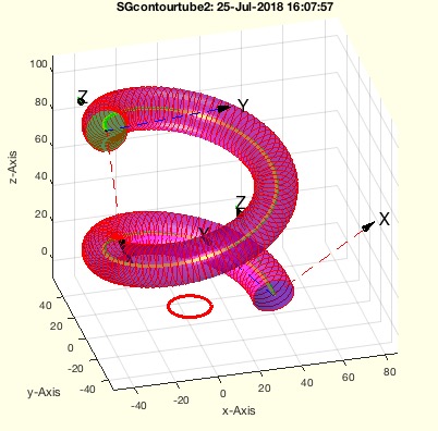 | % SGcontourtube2(CPL,VL) - extrudes a CPL along a path given as CVL % (by Tim Lueth, VLFL-Lib, 2018-JUL-24 as class: SURFACES) % % ======================================================================= % OBSOLETE (2018-08-17) - USE 'SGofCPLtransT' INSTEAD % ======================================================================= % % Improved Version of SGcontourtube % Powerful procedure to extrude PLs [nx2] anlog a path (Status of: % 2018-08-17) % % Introduced first in SolidGeometry 4.2 % % See also: [ SGofCPLtransT ] ; TLofCVL, SGofCPLCVLR, SGcontourtube, % SGofCPLtransT, SGof2T, SGof2SGT, RLofEulerInterpolation, % VLinsertEulerSteps, VLradialEdges, TofPez % % [SG,FLS,FLE,FLW,TS,TE]=SGcontourtube2(CPL,VL) % === INPUT PARAMETERS === % CPL: Closed point list [nx2] % VL: Vertex list [nx3] % === OUTPUT RESULTS ====== % SG: Solid geometry % FLS: FL of starting surface % FLE: FL of ending surface % FLW: FL of the wall % TS: Starting Frame % TE: End Frame % % EXAMPLE: % VL=VLhelix(40,100,3*pi); % SGcontourtube(PLcircle(10),VL) % SGcontourtube2(PLcircle(10),VL) % % See also: [ SGofCPLtransT ] ; TLofCVL, SGofCPLCVLR, SGcontourtube, % SGofCPLtransT, SGof2T, SGof2SGT, RLofEulerInterpolation, % VLinsertEulerSteps, VLradialEdges, TofPez % % % Copyright 2018 Tim C. Lueth |
Rofez(ezz,ystab)- returns a rotation matrix based on a list of ez vector |
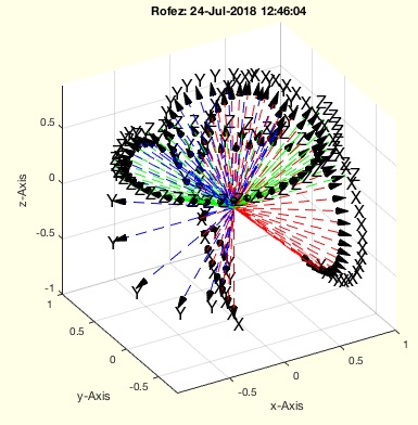 | % Rofez(ezz,ystab) - returns a rotation matrix based on a list of ez vector % (by Tim Lueth, VLFL-Lib, 2018-JUL-23 as class: ANALYTICAL GEOMETRY) % % could be improved in combination with VLedgeNormal (Status of: % 2018-07-24) % % Introduced first in SolidGeometry 4.2 % % See also: VLedgeNormal % % R=Rofez(ezz,[ystab]) % === INPUT PARAMETERS === % ezz: ez vector or list of ez vectors % ystab: true== fix y-axis; false== fix x-axis; default is true; % === OUTPUT RESULTS ====== % R: Rotation matrix or vector of rotation matrices % % EXAMPLE: % Rofez([0 0 1] % Rofez([0 0 1;0 0 -1]) % % See also: VLedgeNormal % % % Copyright 2018 Tim C. Lueth |
SGTofDHset(DHS,r,g)- returns the solids for a kinematic chain defined by DH parameter |
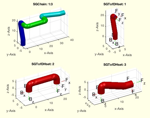 | % SGTofDHset(DHS,r,g) - returns the solids for a kinematic chain defined by DH parameter % (by Tim Lueth, VLFL-Lib, 2018-JUL-20 as class: KINEMATICS AND FRAMES) % % Introduced first in SolidGeometry 4.2 % % See also: SGof2T, SGTset, SGTofDenavitHartenberg, SGTchain % % [SG,Ti,SGN,Tii,E]=SGTofDHset(DHS,[r,g]) % === INPUT PARAMETERS === % DHS: Denavit-Hartenberg Parameter [nx3] [d a wx] or [d a xw xy] % r: optional diameter for tube % g: optional offset for phiz % === OUTPUT RESULTS ====== % SG: Cell list of Solid Geoemtries % Ti: Cell ist of Symbolic Equation % SGN: Compiled Solid using the kinematic chain % Tii: Cell list of complete symbolic equations % E: Final movement matrix of the TCP % % EXAMPLE: SGTofDHset([10 0 pi/2]) % SGTofDHset([20 0 pi/2;0 20 pi;10 0 pi/2; 3 0 pi/4; 3 0 pi/4],1,pi/10); SG=ans % SGTofDHset([20,0,pi/2 0;0 20 pi*0.99 0;0 20 0 pi/2]) % including roation around y % SGTofDHset([20 0 pi/2 0; 0,20,pi 0;0 10 0 pi/2;10 0 pi/4 0; 10 0 -pi/4 0;10 0 0 0]) % SGTofDHset([50 0 0 0; 100,0,pi/2 0;0 100 pi*0.99 0;0 100 0 pi/2],[PLcircle(10);nan nan; PLsquare(12)]); SGA=ans; % SGTofDHset([50 0 0 0; 100,0,pi/2 0;0 100 pi*0.99 0;0 100 0 pi/2],[PLsquare(20);nan nan; PLcircle(7)]); SGA=ans; % % See also: SGof2T, SGTset, SGTofDenavitHartenberg, SGTchain % % % Copyright 2018-2022 Tim C. Lueth |
invkinplan2(l1,l2,PL)- returns the inverse kinematic for a planr 2 arm robot |
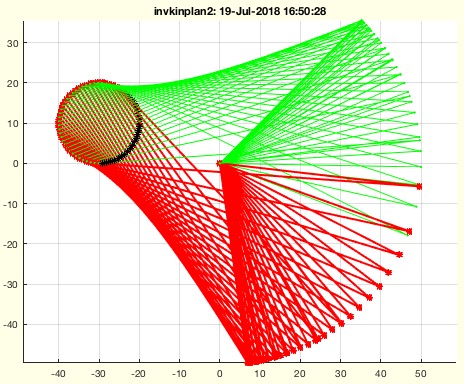 | % invkinplan2(l1,l2,PL) - returns the inverse kinematic for a planr 2 arm robot % (by Tim Lueth, VLFL-Lib, 2018-JUL-19 as class: MECHANICAL PROCEDURES) % % This is just an example how to implement the results of % exp_2018_07_19_invers_kin.mlx into a numeric fnctn. It containts the % closed analytical inverse kinematic for 2 swinging arms. This fnctn can % be used to simulate the movement of fourbar linkages (wrt. Franz % Irlinger) % Format for PL (3rd Parameter): % [] => Cartesian Grid of 100 Points % n => Cartesian Grid of n x n Points % [x y] => Single Point % [r x y] => Radius and location of a crank (60 samples) % [r x y n] => Radius and location of a crank (n samples) % [r x y n s] => Radius and location of a crank (n samples) and angle % segment in degree % [r x y n s w] => Radius and location of a crank (n samples) and segment % and start in degree % (Status of: 2019-05-12) % % Introduced first in SolidGeometry 4.2 % % See also: realfourbarsolutions, checkfourbarsegment, miofPLA0B0, % shiftindexofinvkinplan2, wofcross2circ, invkinrplan3, % exp_2018_07_19_invers_kin.mlx, plot4Bar % % [W,U,B1,B2,rs,PL,ss]=invkinplan2(l1,l2,[PL]) % === INPUT PARAMETERS === % l1: length first link % l2: length second link % PL: Point list (n x 2) or [r dx dy] or [r dx dy n] or % === OUTPUT RESULTS ====== % W: Angle Pair [n x 2] for solution 1 % U: Angle Pair [n x 2] for solution 2 % B1: Endpoint of Arm 1 for solution 1 % B2: Endpoint of Arm 1 for solution 2 % rs: real solutions index; true ~ solution exist % PL: used Point list in case that PL was empty or a triple for a circle % ss: Singularity Index rs&ss % % EXAMPLE: invkinplan2(25,20,[20 20; 25 25;27 27]) % w=0:0.3:2*pi; w=w'; PL=30*[cos(w) sin(w)]; % invkinplan2(20,11,PL) % w=0:0.3:2*pi; w=w'; PL=10*[cos(w) sin(w)]+[-30 +5]; % invkinplan2(30,20,PL) % w=0:0.1:2*pi; w=w'; PL=10*[cos(w) sin(w)]+[-30 10]; invkinplan2(50,80,PL); % invkinplan2(50,80); % Check work space % invkinplan2(50,80,[10 -40 10]); % Check a fourbar linkage % % See also: realfourbarsolutions, checkfourbarsegment, miofPLA0B0, % shiftindexofinvkinplan2, wofcross2circ, invkinrplan3, % exp_2018_07_19_invers_kin.mlx, plot4Bar % % % Copyright 2018-2019 Tim C. Lueth |
SGTofDenavitHartenberg(D,A,be,r,g)- returns from Denavit-Hartenberg values, a solid, frames and a symbolic description for DH |
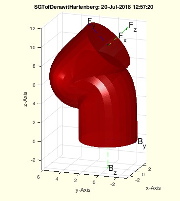 | % SGTofDenavitHartenberg(D,A,be,r,g) - returns from Denavit-Hartenberg values, a solid, frames and a symbolic description for DH % (by Tim Lueth, VLFL-Lib, 2018-JUL-13 as class: MODELING PROCEDURES) % % This fnctn returns for give parameter sets with respect to the % Denavit-Hartenberg (1955) notation: % d=displacement in z % a=displacement in x % b=rotation around x % a modern style link (shape along z trajectory) % 6Dof Roboter lassen sich aus praktischen Gründen (Nutzung und % Berechnung der inversen Kinematik sinnvoller Weise wie folgt entwerfen: % 1. Trennung von Hand und Roboter in je drei Achsen. % 2. Die 6. Achse ist eine möglichst kurze reine Z-Achse. % 3. Die 5. und 4. Achse erlaube eine möglichst kompakte Drehung auf % einer Kugeloberfläche % 4. Die 1. Achse ist eine Z-Achse die so hoch ist dass 2 und 3 optimale % arbeiten können % 5. Die 2 und 3 Achse ind quasi gleich lang. 3 ist kürzer weil 4 und 5 % und 6 noch dazu kommen. % Die inverse Kinematik wird so gelöst, dass ausgehend vom Zielpunkt % z-Achse 6 definiert ist % (Status of: 2018-07-20) % % Introduced first in SolidGeometry 4.2 % % See also: SGTofDHset, SGof2T, SGTset, SGTchain % % [SGT,T]=SGTofDenavitHartenberg(D,A,be,[r,g]) % === INPUT PARAMETERS === % D: Distance in z % A: Distance in z % be: fixed rotation value around x-axis or [x-axis/yaxis] % r: optional Radius of the tube; default is max(D,A)/10 % g: optional angle as offset for a rotation at the base; default is 0 % === OUTPUT RESULTS ====== % SGT: Solid Geoemtry including Frames % T: % % EXAMPLE: Different common robotics links: % SGTofDenavitHartenberg(10,0,0); % SGTofDenavitHartenberg(10,10,0); % SGTofDenavitHartenberg(10,0,pi/2); % SGTofDenavitHartenberg(0,10,pi); % SGTofDenavitHartenberg(10,0,pi/4,3); % SGTofDenavitHartenberg(10,0,pi/2,'',pi/2); % SGTofDenavitHartenberg (0,20,[0,pi/2]); % % See also: SGTofDHset, SGof2T, SGTset, SGTchain % % % Copyright 2018 Tim C. Lueth |
gcahandleofSG- returns the handle to all patches of gca |
 | % gcahandleofSG - returns the handle to all patches of gca % (by Tim Lueth, VLFL-Lib, 2018-JUL-10 as class: VISUALIZATION) % % This fnctn returns the handle to all patches in the current graphics % axis. I tcan be used to change color, transparency, or to create a SG. % (Status of: 2018-07-19) % % Introduced first in SolidGeometry 4.2 % % See also: ispatch, SGofgca % % h=gcahandleofSG % === OUTPUT RESULTS ====== % h: handle of all patches in gca % % EXAMPLE: % SGfigure; view(-30,30); SGplot(SGbox([30,20,10])); % setplotlight(gcahandleofSG,'b',0.2), show % % See also: ispatch, SGofgca % % % Copyright 2018 Tim C. Lueth |
subsvar(f,sv,)- replaces several symbols in an equation |
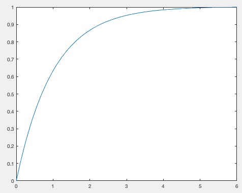 | % subsvar(f,sv,) - replaces several symbols in an equation % (by Tim Lueth, VLFL-Lib, 2018-JUN-29 as class: SYMBOLICS) % % This fnctn is required to substitute several symbols or terms in a % symbolic equation (Status of: 2018-06-29) % % Introduced first in SolidGeometry 4.2 % % g=subsvar(f,sv,[]) % === INPUT PARAMETERS === % f: original term / equation % sv: array of symbols to substitute or [s1 v1; s2 z2]; % === OUTPUT RESULTS ====== % g: resulting term / equation % % EXAMPLE: % syms x(t) D C F m; dx=diff(x); ddx=diff(x,2); % f=dsolve(m*ddx+D*dx==0, x(0)==0,x(6)==1); sv=symvar(f) % subsvar(f,[D m],[1 1]) % subsvar(f,[D 1;m 1]) % % % Copyright 2018 Tim C. Lueth |
VLFLvertexNormal(VL,FL,vi)- returns the vertex normal for the vertices of a solid |
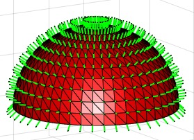 | % VLFLvertexNormal(VL,FL,vi) - returns the vertex normal for the vertices of a solid % (by Yilun Sun, CT-Image, 2018-JUN-21 as class: ANALYTICAL GEOMETRY) % % This fnctn calculates the vertex normal from the average normal of the % surrounding facets weighted by the corresponding angles. % Arrows are drawn only up to 100 vertices % - This fnctn may be can accelerated by triangulating only the facet % attached to the vertices (TL) (Status of: 2018-08-25) % % Introduced first in SolidGeometry 4.2 % % See also: vertexNormalbyFN, PLnorm, PLELnorm, PLFLfaceNormal, VLnorm, % VLFLnormf, VLFLfaceNormal, VLedgeNormal, VLFLfaceAngles % % LITERATURE: % - Grit Thuermer and Charles A. Wuethrich (1998): "Computing vertex % normals from polygonal facets", Journal of Graphics Tools, Volume 3 % Issue 1, Mar 1998, Pages 43-46 % % NVL=VLFLvertexNormal(VL,FL,[vi]) % === INPUT PARAMETERS === % VL: Vertex list % FL: Facet list % vi: optional vertex index; default is all % === OUTPUT RESULTS ====== % NVL: Normal Vector List [nf x 3] % % EXAMPLE: % [VL,FL]=SGsample(4); VLFLvertexNormal(VL,FL); % [VL,FL]=SGsample(5); VLFLvertexNormal(VL,FL); % [VL,FL]=VLFLsample(11); VLFLvertexNormal(VL,FL) % % See also: vertexNormalbyFN, PLnorm, PLELnorm, PLFLfaceNormal, VLnorm, % VLFLnormf, VLFLfaceNormal, VLedgeNormal, VLFLfaceAngles % |
usedinEL(NEL)- returns a list of unique numbers and the number of use in the list |
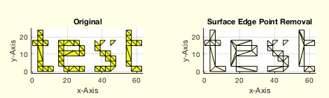 | % usedinEL(NEL) - returns a list of unique numbers and the number of use in the list % (by Tim Lueth, VLFL-Lib, 2018-JUN-02 as class: AUXILIARY PROCEDURES) % % Auxiliary fnctn for searching in non manifold or corrupted edge lists % (Status of: 2019-06-30) % % Introduced first in SolidGeometry 4.2 % % See also: graphofEL, ELplot % % PIL=usedinEL(NEL) % === INPUT PARAMETERS === % NEL: Any kind of list of integers, such as EL, FL % === OUTPUT RESULTS ====== % PIL: Entry index list [Entry number] % % EXAMPLE: % CPLoftext('test'); CPL=ans; % Create contours % CPL=rounddiv(CPL,3); % Grid will create non manifold edges % SGfigure; CPLplot(CPL); [PL,EL]=PLELofCPL(CPL); % [PL,EL]=VLELshort(PL,EL); % removed doubled used points % EL=unique(EL,'rows','stable'); % remove doubled edges % EL=EL(EL(:,1)~=EL(:,2),:) % remove point type edges % usedinEL(EL) % TR=delaunayTriangulation(PL,EL); % SGfigure; VLFLplot(TR.Points,TR.ConnectivityList(isInterior(TR),:)) % B.VL=VLaddz(TR.Points); B.FL=TR.ConnectivityList(isInterior(TR),:) % B=SGshort(B); % remove unused points % SGremsurfedgepoints(B) % % See also: graphofEL, ELplot % % % Copyright 2018-2019 Tim C. Lueth |
FEsort(FEL)- groups and sorts unsorted edge lists |
 | % FEsort(FEL) - groups and sorts unsorted edge lists % (by Tim Lueth, VLFL-Lib, 2018-APR-18 as class: EDGE LISTS) % % ======================================================================= % OBSOLETE (2018-04-18) - USE 'ELsortFE' INSTEAD % ======================================================================= % % Same as ELsortFE % Feature Edge lists are unsorted and not directed. This fnctns separates % the edge lists into groups of meshes and contours and sorts contours % into one direction. There is no guarantee that it is the right % direction since the vertices are unknown to this fnctn. (Status of: % 2018-04-18) % % Introduced first in SolidGeometry 4.2 % % [EL,CEL,mi]=FEsort(FEL) % === INPUT PARAMETERS === % FEL: Unsorted edge list for instance a feature edge list % === OUTPUT RESULTS ====== % EL: Edge list % CEL: Contour index list % mi: mesh index; false = contour, true is mesh % % EXAMPLE: % FEsort(FEofSG(SGsample(32))) % % % Copyright 2018 Tim C. Lueth |
ELsortFE(FEL)- groups and sorts unsorted edge lists |
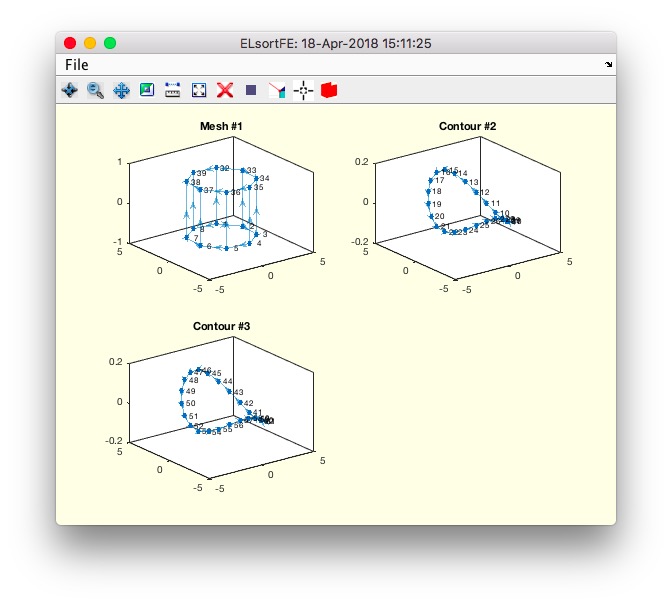 | % ELsortFE(FEL) - groups and sorts unsorted edge lists % (by Tim Lueth, VLFL-Lib, 2018-APR-18 as class: EDGE LISTS) % % Feature Edge lists are unsorted and not directed. This fnctns separates % the edge lists into groups of meshes and contours and sorts contours % into one direction. There is no guarantee that it is the right % direction since the vertices are unknown to this fnctn. (Status of: % 2018-04-18) % % Introduced first in SolidGeometry 4.2 % % See also: ELconnectedgroups, CELofEL % % [EL,CEL,mi]=ELsortFE(FEL) % === INPUT PARAMETERS === % FEL: Unsorted edge list for instance a feature edge list % === OUTPUT RESULTS ====== % EL: Edge list % CEL: Contour index list % mi: mesh index; false = contour, true is mesh % % EXAMPLE: % ELsortFE(FEofSG(SGsample(32))) % % See also: ELconnectedgroups, CELofEL % % % Copyright 2018 Tim C. Lueth |
PLchamfer(z,ph,sh,d)- returns a point list for chamfer shape fncts |
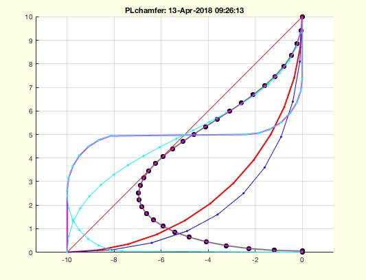 | % PLchamfer(z,ph,sh,d) - returns a point list for chamfer shape fncts % (by Tim Lueth, VLFL-Lib, 2018-APR-11 as class: CLOSED POLYGON LISTS) % % written in Al-Dakhla, Marocco, % From a z value and a phase distance, several different curves are % calculate that can be used to create chamfers of 2.5D solids using % fnctn SGchamfer % line - direct chamfer % circ - 90 degree chamfer % circ2 - 90/-90 degree chamfer % circ3 - 90/-90/90 degree chamfer % bezier - 90 degree Bezier spline % bezier2 - 90/-90 degree Bezier spline % bezier3 - 90/-90/90 degree Bezier spline % mattheck - zugdreieck-methode nach mattheck ~ tan(0..1.32) % (Status of: 2021-01-02) % % Introduced first in SolidGeometry 4.2 % % See also: SGchamfer, PLchamfer2side % % PL=PLchamfer([z,ph,sh,d]) % === INPUT PARAMETERS === % z: height % ph: chamfer thickness % sh: shape such as 'line', 'circ' % d: value for straight end distance % === OUTPUT RESULTS ====== % PL: Point list for a chamfer design % % EXAMPLE: % PLchamfer(10,-10) % PLchamfer(10,-10,'circ') % PLchamfer(10,-10,'bezier') % cla; PL=[PLchamfer(10,+10,'mattheck')+[10 0]; 0 10; 0 0; ], CPLplot(PL); SGofCPLrot(PL) % % See also: SGchamfer, PLchamfer2side % % % Copyright 2018-2021 Tim C. Lueth |
SGfiguremovie(fname,mtime,angle,ofs)- creates a movie from a simple rotating view point in MP4 Format |
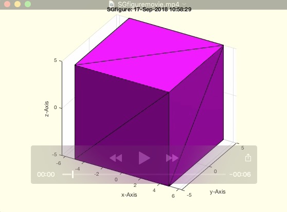 | % SGfiguremovie(fname,mtime,angle,ofs) - creates a movie from a simple rotating view point in MP4 Format % (by Tim Lueth, VLFL-Lib, 2018-MÄR-12 as class: VISUALIZATION) % % ======================================================================= % OBSOLETE (2022-02-01) - USE 'Videoquickstart, figurerotate, % Videoquickcloseandopen' INSTEAD % ======================================================================= % % This fnctn is also helpful to learn to create movies from figure % snapshots % 2018-04-17 Default format changed from 'AVI' to 'MPEG-4' % (Status of: 2021-01-04) % % Introduced first in SolidGeometry 4.2 % % See also: [ Videoquickstart, figurerotate, Videoquickcloseandopen ] ; % getgcatitle, imageVideoWrite, SGfigurevideo, SGfigure, SGtitle, % SGfigureannotation, imageVideoEndtitle, imageVideoFrames, % imageVideoTextPage, imageVideoTitle, videoCopyCutMovies, % videoCopyFrames, figurerotate % % SGfiguremovie([fname,mtime,angle,ofs]) % === INPUT PARAMETERS === % fname: file name on desktop; default is 'SGfiguremovie.avi' % mtime: movie time; default is 6 seconds % angle: turning angle; default is [10 370] % ofs: offset to start angle; default is 0 % % EXAMPLE: % SGsample(25); % SGfiguremovie % SGfiguremovie('',3) % SGfiguremovie('',3,[-20 20]) % % % See also: [ Videoquickstart, figurerotate, Videoquickcloseandopen ] ; % getgcatitle, imageVideoWrite, SGfigurevideo, SGfigure, SGtitle, % SGfigureannotation, imageVideoEndtitle, imageVideoFrames, % imageVideoTextPage, imageVideoTitle, videoCopyCutMovies, % videoCopyFrames, figurerotate % % % Copyright 2018-2022 Tim C. Lueth |
SGfigureannotation(str,bc,sz,sl,hl)- creates a simple help text annotation into the current figure |
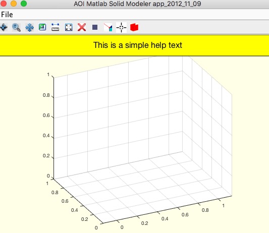 | % SGfigureannotation(str,bc,sz,sl,hl) - creates a simple help text annotation into the current figure % (by Tim Lueth, VLFL-Lib, 2018-MÄR-12 as class: USER INTERFACE) % % Used in fnctns such as SGTui (Status of: 2020-10-10) % % Introduced first in SolidGeometry 4.2 % % See also: plotannotation, SGfigurevideo, SGfigure, SGtitle, % titleofcaller, annotation, SGhelptext % % h=SGfigureannotation(str,[bc,sz,sl,hl]) % === INPUT PARAMETERS === % str: string % bc: backgoundcolor; default is unchanged % sz: text size; default is 10 % sl: starting position from bottom; default is 0.97% % hl: height of annotation; default is 1-sl % === OUTPUT RESULTS ====== % h: handle to annotation % % EXAMPLE: % SGfigure; % SGfigureannotation('This is a simple help text','y',16,0.9) % % See also: plotannotation, SGfigurevideo, SGfigure, SGtitle, % titleofcaller, annotation, SGhelptext % % % Copyright 2018-2020 Tim C. Lueth |
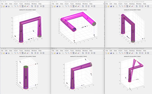
SGplot4(SG,)- plots a solid in 4 views |
 | % SGplot4(SG,) - plots a solid in 4 views % (by Tim Lueth, VLFL-Lib, 2018-MÄR-08 as class: VISUALIZATION) % % Introduced first in SolidGeometry 4.2 % % See also: VLFLplot4, SGplot % % SGplot4(SG,[]) % === INPUT PARAMETERS === % SG: Solid Geometry % % EXAMPLE: SGplot4(SGsample(25),'m') % % See also: VLFLplot4, SGplot % % % Copyright 2018 Tim C. Lueth |
VLFLremsurfedgepoints(VL,FL,alpha,minf)- returns a surface model without edge points and surface points that are inside of a surface |
 | % VLFLremsurfedgepoints(VL,FL,alpha,minf) - returns a surface model without edge points and surface points that are inside of a surface % (by Tim Lueth, VLFL-Lib, 2018-MÄR-06 as class: SURFACES) % % Calls fnctn as SGremsurfedgepoints. This fnctn is useful if a % tetrahedron model (pde mesh) is converted into a surface model, or a % solid is bent somehow. Afterwards there a surfaces that consist of many % vertices that are in the same plane. This fnctn analyses the surface % and retesselate all surface based only on the boundary vertices. % (Status of: 2018-03-06) % % Introduced first in SolidGeometry 4.2 % % See also: VLFLremsurfpoints, SGremsurfpoints, SGofpdemodel, % SGremsurfedgepoints % % [VLN,FLN,FLNorg,FSi]=VLFLremsurfedgepoints(VL,FL,[alpha,minf]) % === INPUT PARAMETERS === % VL: Vertex list of surface model % FL: Facet list of surface model % alpha: alpha angle for feature surface; default is 0.01 % minf: minimum facets per face; default is 4 % === OUTPUT RESULTS ====== % VLN: New vertex list surface model with reduced vertices % FLN: New facet list surface model with reduced vertices % FLNorg: Reduced Facet list based on the original vertex list % FSi: Feature surface index list % % EXAMPLE: Remove surface and edge points % A=SGbox([30,20,10]) % model=pdemodelofSG(A,5) % SGofpdemodel(model); B=ans; VL=B.VL; FL=B.FL; % VLFLremsurfedgepoints(B.VL,B.FL) % % See also: VLFLremsurfpoints, SGremsurfpoints, SGofpdemodel, % SGremsurfedgepoints % % % Copyright 2018 Tim C. Lueth |
ELremove(EL,indl)- removes an index from an unsorted edge list |
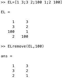 | % ELremove(EL,indl) - removes an index from an unsorted edge list % (by Tim Lueth, VLFL-Lib, 2018-MÄR-06 as class: EDGE LISTS) % % throws an error if an index list element is not part of the edge list % (Status of: 2018-03-06) % % Introduced first in SolidGeometry 4.2 % % See also: ELsort % % ELN=ELremove(EL,indl) % === INPUT PARAMETERS === % EL: original unsorted edge list % indl: index to be removed, or index list % === OUTPUT RESULTS ====== % ELN: new unsorted edge list without the index % % EXAMPLE: remove one index % EL=[1 3;3 2;100 1;2 100] % ELremove(EL,100) % ELremove(EL,[1 2]) % % See also: ELsort % % % Copyright 2018 Tim C. Lueth |
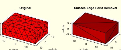
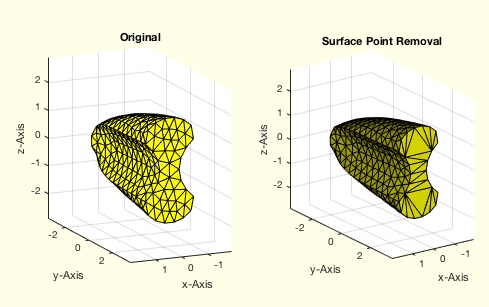
SGremsurfedgepoints(SG,alpha,minf)- returns a surface model without edge points and surface points that are inside of a surface |
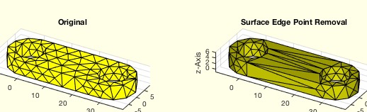 | % SGremsurfedgepoints(SG,alpha,minf) - returns a surface model without edge points and surface points that are inside of a surface % (by Tim Lueth, VLFL-Lib, 2018-MÄR-06 as class: SURFACES) % % This fnctn is useful if a tetrahedron model (pde mesh) is converted % into a surface model, or a solid is bent somehow. Afterwards there a % surfaces that consist of many vertices that are in the same plane. This % fnctn analyses the surface and retesselate all surface based only on % the boundary vertices. % IN ADDITION THIS FNCTNS OPTIMIZES THE TRIANGLES BY RETESSELATION % (Status of: 2020-12-13) % % Introduced first in SolidGeometry 4.2 % % See also: VLFLremsurfpoints, SGremsurfpoints, SGofpdemodel % % [SGN,FLN,FSi]=SGremsurfedgepoints(SG,[alpha,minf]) % === INPUT PARAMETERS === % SG: Solid Geometry surface model % alpha: alpha angle for feature surface; default is 0.01 % minf: minimum facets per face; default is 5; smalles value % === OUTPUT RESULTS ====== % SGN: New surface model with reduced vertices and faces % FLN: Reduced Facet list based on the original vertex list % FSi: Feature surface index list % % EXAMPLE: Remove surface points and points on the line: % A=SGlinkage(5,30,5) % model=pdemodelofSG(A,1) % SGofpdemodel(model); B=ans % SGremsurfedgepoints(B) % SGremsurfedgepoints(SGsphere(10),0.1); % 0.1 makes sense % % See also: VLFLremsurfpoints, SGremsurfpoints, SGofpdemodel % % % Copyright 2018-2021 Tim C. Lueth |
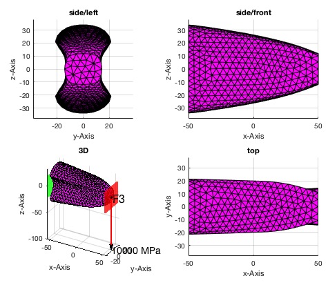
SGplotsurfaceload (SG,fixfacet,loadfacet,loadvec)- plots the surface load of a solid geometry |
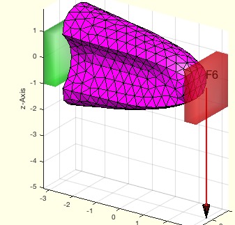 | % SGplotsurfaceload (SG,fixfacet,loadfacet,loadvec) - plots the surface load of a solid geometry % (by Tim Lueth, VLFL-Lib, 2018-MÄR-03 as class: FEM/PDE) % % This fnctn displays the surfaceload sitation that is used as input for % the fnctns: % pdesolvesurfaceload % pdestressstatic % SGshapeOptiCAO % % (Status of: 2018-03-23) % % Introduced first in SolidGeometry 4.2 % % See also: pdestressstatic, pdesolvesurfaceload, SGshapeOptiCAO % % SGplotsurfaceload(SG,[fixfacet,loadfacet,loadvec]) % === INPUT PARAMETERS === % SG: Solid Geometry % fixfacet: list of fix Feature surfaces (green) % loadfacet: list of loaded Feature surfaces (red) % loadvec: vector of load per Feature surface % === PROPERTY NAMES ===== % 'FixedFaceIndices' : the face indices of the faces which are fixed % 'LoadFaceIndices' : the face indices of the faces which are loaded % 'Load' : the load list according to LoadFaceIndices(unit of load is N) % % EXAMPLE: % A=SGbox([100,40,40]); SGfigure; % subplot(1,2,1); FSplot(A); view(30,30); % subplot(1,2,2); SGplotsurfaceload(A,[4 5],3,1e4); view(30,30); % % SGfigure; h=SGplot(A); setplotlight(h,'w',0.8); % SGplotsurfaceload(A,4,3,[0 -1e4 0]); view(30,30) % % SGfigure; h=SGplot(A); setplotlight(h,'w',0.8); view(30,30); % SGplotsurfaceload (A,'FixedFaceIndices',4,... % 'LoadFaceIndices',[3 3 NaN 5],'Load',[0 0 -4; 0 0 6; NaN NaN NaN;0 -2 % 0]) % % % % See also: pdestressstatic, pdesolvesurfaceload, SGshapeOptiCAO % % % Copyright 2018 Tim C. Lueth |
VLFLremsurfpoints(VL,FL,)- returns a surface model without surface points that are inside of a surface - boundary/edge points are unchanged |
 | % VLFLremsurfpoints(VL,FL,) - returns a surface model without surface points that are inside of a surface - boundary/edge points are unchanged % (by Tim Lueth, VLFL-Lib, 2018-MÄR-02 as class: SURFACES) % % Calls fnctn as SGremsurfpoints. This fnctn is useful if a tetrahedron % model (pde mesh) is converted into a surface model, or a solid is bent % somehow. Afterwards there a surfaces that consist of many vertices that % are in the same plane. This fnctn analyses the surface and retesselate % all surface based only on the boundary vertices. (Status of: 2018-03-02) % % Introduced first in SolidGeometry 4.2 % % See also: VLFLremsurfpoints, SGremsurfpoints, SGofpdemodel % % [VLN,FLN,FLNorg,FSi]=VLFLremsurfpoints(VL,FL,[]) % === INPUT PARAMETERS === % VL: Vertex list of surface model % FL: Facet list of surface model % === OUTPUT RESULTS ====== % VLN: New vertex list surface model with reduced vertices % FLN: New facet list surface model with reduced faces % FLNorg: Reduced Facet list based on the original vertex list % FSi: Feature surface index list % % EXAMPLE: Remove surface points % A=SGbox([30,20,10]) % model=pdemodelofSG(A,5) % SGofpdemodel(model); B=ans; VL=B.VL; FL=B.FL; % SGremsurfpoints(B) % % See also: VLFLremsurfpoints, SGremsurfpoints, SGofpdemodel % % % Copyright 2018 Tim C. Lueth |
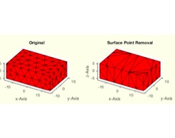
SGremsurfpoints(SG,alpha)- returns a surface model without surface points that are inside of a surface - boundary/edge points are unchanged |
 | % SGremsurfpoints(SG,alpha) - returns a surface model without surface points that are inside of a surface - boundary/edge points are unchanged % (by Tim Lueth, VLFL-Lib, 2018-MÄR-02 as class: SURFACES) % % This fnctn is useful if a tetrahedron model (pde mesh) is converted % into a surface model, or a solid is bent somehow. Afterwards there a % surfaces that consist of many vertices that are in the same plane. This % fnctn analyses the surface and retesselate all surface based only on % the boundary vertices. (Status of: 2018-03-02) % % Introduced first in SolidGeometry 4.2 % % See also: VLFLremsurfpoints, SGofpdemodel % % [SGN,FLN,FSi]=SGremsurfpoints(SG,[alpha]) % === INPUT PARAMETERS === % SG: Solid Geometry surface model % alpha: alpha angle for feature surface; default is 0.01 % === OUTPUT RESULTS ====== % SGN: New surface model with reduced vertices and faces % FLN: Reduced Facet list based on the original vertex list % FSi: Feature surface index list % % EXAMPLE: Remove surface points % A=SGbox([30,20,10]) % model=pdemodelofSG(A,5) % SGofpdemodel(model); B=ans % SGremsurfpoints(B) % % See also: VLFLremsurfpoints, SGofpdemodel % % % Copyright 2018 Tim C. Lueth |
SGofpdemodel(model)- returns a solid geometry surface model of a pde model |
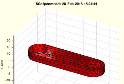 | % SGofpdemodel(model) - returns a solid geometry surface model of a pde model % (by Tim Lueth, VLFL-Lib, 2018-FEB-28 as class: FEM/PDE) % % the tetrahedron models of the model.Mesh are used to create a % tetrahedron triangulation. The freeboundary surface of this model is % used to create the surface model. % In contrast to tetramesh, the tetrahedrons in 3D pde models have 11 % vertices. (Status of: 2018-02-28) % % Introduced first in SolidGeometry 4.2 % % See also: pdemodelofSG, SGtetramesh, SGremsurfpoints % % SG=SGofpdemodel(model) % === INPUT PARAMETERS === % model: pde model created by pdemodelofSG % === OUTPUT RESULTS ====== % SG: Solud Geometry surface model % % EXAMPLE: % A=SGlinkage(5,40,5) % model=pdemodelofSG(A,1) % SGofpdemodel(model) % % See also: pdemodelofSG, SGtetramesh, SGremsurfpoints % % % Copyright 2018 Tim C. Lueth |
VLFLplotfacets(VL,FL)- plot a facet list as separate independent facets |
 | % VLFLplotfacets(VL,FL) - plot a facet list as separate independent facets % (by Tim Lueth, VLFL-Lib, 2018-FEB-28 as class: SURFACES) % % Introduced first in SolidGeometry 4.2 % % See also: VLFLplot % % h=VLFLplotfacets(VL,FL) % === INPUT PARAMETERS === % VL: Vertex list or SG % FL: Facet list % === OUTPUT RESULTS ====== % h: handle list of all facets % % EXAMPLE: loadweb JACO_robot.mat % SGfigure; VLFLplotfacets(JCF) % setplotlight(h,'w',0.4) % % See also: VLFLplot % % % Copyright 2018 Tim C. Lueth |
SGofFS(SG,alp,fsi,t,d,s)- returns a list of solid geometries that are attached to features surfaces |
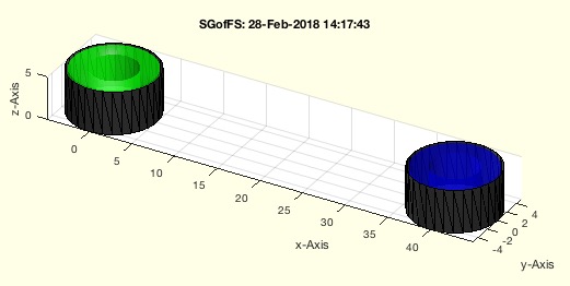 | % SGofFS(SG,alp,fsi,t,d,s) - returns a list of solid geometries that are attached to features surfaces % (by Tim Lueth, VLFL-Lib, 2018-FEB-28 as class: SURFACES) % % This fnctn is more ore less the same as SGofSurface, but the surfaces % are addressed as Feature Surfaces. This fnctn is an auxiliary fnctn to % create pretty (more visible) representations of surfaces (Status of: % 2018-02-28) % % Introduced first in SolidGeometry 4.2 % % See also: SGofSurface, FSofSG % % [SGc,FSc]=SGofFS(SG,[alp,fsi,t,d,s]) % === INPUT PARAMETERS === % SG: Solid geometry % alp: alpha angle to calculate the feature surfaces; default is 1 % fsi: feature surface list; default is all % t: thickness of the solid; default is 0.5 used in SGofSurface % d: distance from the surface; default is 0.3 used in SGofSurface % s: distance from the surface; default is 0.3 used in SGofSurface % % === OUTPUT RESULTS ====== % SGc: Cell list of Solids related to fsi % FSc: Cell list of Vertex list and facet list of the FS related to fsi % % EXAMPLE: % A=SGlinkage(5,40,5) % SGofFS(A,[],[4 5],2); % % % See also: SGofSurface, FSofSG % % % Copyright 2018 Tim C. Lueth |
SGshapeOptiCAO(SG,)- returns the optimized shape of a given structure based on biological growth |
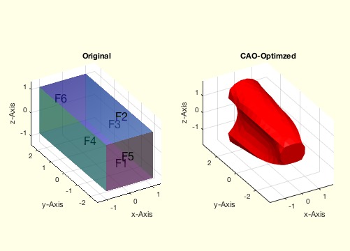 | % SGshapeOptiCAO(SG,) - returns the optimized shape of a given structure based on biological growth % (by Yilun Sun, VLFL-Lib, 2018-FEB-22 as class: FEM/PDE) % % The principle of the procedure is to allow the design proposal for the % desired component to grow into a shape of constant von Mises stress at % its surface. % It is possible to consider different load situations. In this case % (Status of: 2018-03-05) % % Introduced first in SolidGeometry 4.2 % % See also: pdestressstatic, SGplotsurfaceload, FSplot % % LITERATURE: % - Harzheim, Lothar (2014): Strukturoptimierung - Grundlagen und % Anwendungen, Europa Lehrmittel. % % [SG,result,model,IterationAnalysis]=SGshapeOptiCAO(SG,[]) % === INPUT PARAMETERS === % SG: Solid Geometry of the initial design proposal(unit is mm) % === PROPERTY NAMES ===== % 'MaxElementSize' : the maximal length of meshing element; def=1 % 'LoadFaceIndices' : the face indices of the faces which are loaded % 'Load' : the load list according to LoadFaceIndices(unit of load is N) % 'FixedFaceIndices' : the face indices of the faces which are fixed % 'NonOptFaceIndices' : the face indices of the faces which are not to be % optimized % 'IterationNumber' : the maximal iterations for the optimization, def 30 % === OUTPUT RESULTS ====== % SG: Solid Geometry of the optimized structure % result: FEM anaysis result of the optimized structure(from PDE Toolbox) % model: pdemodel of the optimized structure(from PDE Toolbox) % IterationAnalysis: logged information of every optimization iteration % % EXAMPLE: % SG1 = SGbox([2,5,2]); % SGshapeOptiCAO(SG1,'MaxElementSize',0.4,'LoadFaceIndices',[5],... % 'Load',[0 0 -4],'FixedFaceIndices',6); % % [SG2,result,model,IA] = SGshapeOptiCAO(SG1,'MaxElementSize',0.4,... % 'LoadFaceIndices',[6],'Load',[0 0 -4],'FixedFaceIndices',5); % SGfigure(SG2); % % SGshapeOptiCAO(SG1,'MaxElementSize',0.4,... % 'LoadFaceIndices',[6 NaN 6],... % 'Load',[0 0 -4;NaN NaN NaN;0 0 5],'FixedFaceIndices',5); % % % See also: pdestressstatic, SGplotsurfaceload, FSplot % % |
pdestressstatic(model,result,inputParser)- returns the calculated static stress inside a SG based on a pde model |
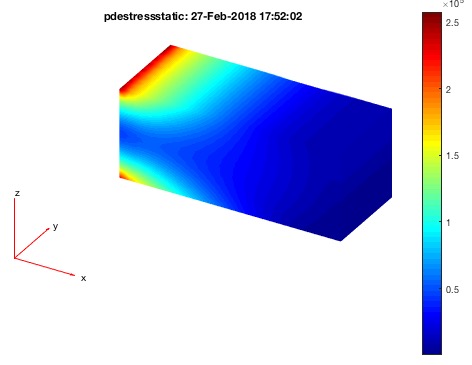 | % pdestressstatic(model,result,inputParser) - returns the calculated static stress inside a SG based on a pde model % (by Yilun Sun, VLFL-Lib, 2018-FEB-22 as class: FEM/PDE) % % This fnctn calculates the static von-Mises stress inside the SG. % By default, the model mesh is used for stress caluclation. % If only a few points are of interest, use a vertex list as optional % input parameter. In this case, the calculation is done for any points % (also outside of the grid) but there will by no graphical output. % (Status of: 2018-02-28) % % Introduced first in SolidGeometry 4.2 % % See also: pdemodelofSG, pdeplotfaces, pdesolvesurfaceload, pdeplotresult % % [stresstensor,sVonMises]=pdestressstatic(model,result,[inputParser]) % === INPUT PARAMETERS === % model: pde-model (attention: modified / call by reference) % result: simulation result of fnctn pdesolvesurfaceload % inputParser: see Property Names % === PROPERTY NAMES ===== % 'FaceAlpha' : Alpha value, default is 1 % 'Points' : Vertex list [nx3], default is empty % 'Plot' : 'on' or 'off', default is 'off' % === OUTPUT RESULTS ====== % stresstensor: List of stress tensors % sVonMises: static von-Mises stress % % EXAMPLE: Simple Load Example: % A=SGbox([100,40,40]) % model=pdemodelofSG(A,5); % [result, model]=pdesolvesurfaceload(model,4,2,1e4) % pdeplotresult(model,result) % pdestressstatic(model,result) % % See also: pdemodelofSG, pdeplotfaces, pdesolvesurfaceload, pdeplotresult % |
SGshapeOptiSKO(SG,)- plots the surface load of a solid geometry |
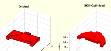 | % SGshapeOptiSKO(SG,) - plots the surface load of a solid geometry % (by Yilun Sun, VLFL-Lib, 2018-FEB-22 as class: FEM/PDE) % % ======================================================================= % WORK IN PROGRESS (2018-03-05) - NOT READY FOR FINAL RELEASE % ======================================================================= % % This fnctn displays the surfaceload sitation that is used as input for % the fnctns: % pdesolvesurfaceload % pdestressstatic % SGshapeOptiCAO % % (Status of: 2018-03-05) % % Introduced first in SolidGeometry 4.2 % % See also: pdestressstatic, pdesolvesurfaceload, SGshapeOptiCAO % % [SG2,resultSKO]=SGshapeOptiSKO(SG,[]) % === INPUT PARAMETERS === % SG: Solid Geometry % === PROPERTY NAMES ===== % 'MaxElementSize' : the face indices of the faces which are fixed % 'LoadFaceIndices' : the face indices of the faces which are loaded % 'Load' : the load list according to LoadFaceIndices(unit of load is N) % 'FixedFaceIndices' : % 'IterationNumber' : % 'FixedDomain' : % 'VolumeConstraint' : % === OUTPUT RESULTS ====== % SG2: % resultSKO: % % EXAMPLE: PL1 = [0 0;1 0;1 1;9 1;9 0;10 0;10 5;6 5;6 6;4 6;4 5;0 5]; % SG1 = SGofCPLz(PL1,1); % h = 0.4; % iFixedFace = [3 11]; % iLoadFace = 7; % Load = [0 -200 0]; % FixedDomain = {[0 10;0 0.9;0 1]}; % niter = 8; % VolPer = 0.75; % resultSKO = % TopologyOptiSKO(SG1,'MaxElementSize',h,'FixedFaceIndices',iFixedFace,... % 'LoadFaceIndices',iLoadFace,'Load',Load,'IterationNumber',niter,... % 'VolumeConstraint',VolPer,'FixedDomain',FixedDomain); % % % See also: pdestressstatic, pdesolvesurfaceload, SGshapeOptiCAO % |
SGofCPLrota(CPL,alp,mov,amin,h)- returns a solid geometry by rotateing a closed x z contour around z axis |
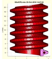 | % SGofCPLrota(CPL,alp,mov,amin,h) - returns a solid geometry by rotateing a closed x z contour around z axis % (by Tim Lueth, VLFL-Lib, 2017-OKT-18 as class: SURFACES) % % Introduced first in SolidGeometry 4.2 % % See also: SGofCPLz, SGofCPLsphere, SGbeating, SGofCPLT, SGofCPLrot, % SGofCPLzchamfer % % [VL,FL]=SGofCPLrota(CPL,[alp,mov,amin,h]) % === INPUT PARAMETERS === % CPL: Closed contour in [x z] % alp: sweeping angle % mov: false = cut; negative x values; true=move to zero % amin: angle offset; default is 0 % h: optional height to create gear worms etc. % === OUTPUT RESULTS ====== % VL: Vertex list or SG % FL: Facet list % % EXAMPLE: SGofCPLrota(CPLsample(31),1.5*pi); % SGofCPLrota(PLcircle(10),1.5*pi,false); % SGofCPLrota(PLcircle(10),1.5*pi,true); % PLtrans0(PLgearrackDIN(1,1)); PL=ans; PL=PL-[0 min(PL(:,2))]; PLplot(PL,'b-') % SGofCPLrota(CPLofPL(PL(:,[2 1])+[5 0]),12*pi,false,'',20); % PLtrans0(PLgearrackDIN(1,1)); PL=[ans;nan nan; PLcircle(0.5)]; PL=PL-[0 min(PL(:,2))]; PLplot(PL,'b-') % SGofCPLrota(CPLofPL(PL(:,[2 1])+[5 0]),12*pi,false,'',20); % % See also: SGofCPLz, SGofCPLsphere, SGbeating, SGofCPLT, SGofCPLrot, % SGofCPLzchamfer % % % Copyright 2017-2018 Tim C. Lueth |