by Tim C. Lueth, SG-Lib Toolbox: SolidGeometry 5.6 - ENG-Components
Introduced first in SolidGeometry 4.7, Creation date: 2019-07-15, Last change: 2025-08-18
SG=SGbitISO1173([n,l,d])
n: | ||
l: | ||
d: |
SG: | Solid Geometry |
SGbitISO1173
SGbitISO1173(4)This function, SGbitISO1173, is designed to create a solid geometry model of a bit according to the DIN 3126 ISO 1173 standard. The function takes several input parameters and returns a solid geometry object.
getfuncparams function. It sets default values if parameters are not provided:
d is set to 6.3 mm, which is equivalent to 1/4 inch.l is set to 15 mm.n is set to 6.r1 is calculated using the formula r1 = dofn(n) * d / 2. The function dofn is assumed to determine a factor based on n.SG is created using the function SGofCPLzchamfer with the following parameters:
PLcircle(r1, n): Creates a circular profile with radius r1 and n segments.l: The length of the bit.1: Chamfer parameter.false: A boolean parameter, possibly for chamfer direction or type.SGTset is used to set transformation properties of the solid geometry:
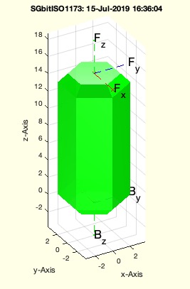
'B' with vector [0 0 -1]: Sets a base transformation.'F' with vector [0 0 +1]: Sets a forward transformation.nargout == 0), the function visualizes the solid geometry:
SGfigure: Initializes a figure for plotting.view(-30, 30): Sets the view angle for the plot.SGplotalpha(SG, 'g', 0.9): Plots the solid geometry with green color and 90% transparency.SGTframeplot(SG): Plots the transformation frame of the solid geometry.