SGtorquefuse
by Tim C. Lueth, SG-Lib Toolbox: SolidGeometry 5.6 - Parametric Design
Introduced first in SolidGeometry 4.7, Creation date: 2019-07-09, Last change: 2025-08-19
returns a SG consisting of three parts to implement a clutch
See Also: SGof2T
, SGof2SGT
, SGsnaprivet
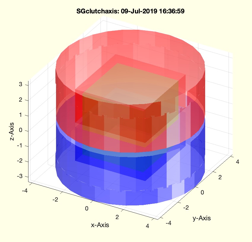
Example Illustration
Syntax
SGC=SGtorquefuse([dim,wt])
Input Parameter
Output Parameter
Examples
SGtorquefuse
Copyright 2019-2025 Tim C. Lueth. All rights reserved. The code is the property of Tim C. Lueth and may not be redistributed or modified without explicit written permission. This software may be used free of charge for academic research and teaching purposes only. Commercial use, redistribution, modification, or reverse engineering is strictly prohibited. Access to source code is restricted and granted only under specific agreements. For licensing inquiries or commercial use, please contact: Tim C. Lueth
Algorithm (Workflow)
This function, SGtorquefuse, is designed to create a clutch geometry using parametric design principles. It is part of the SolidGeometry library and was introduced in version 4.7. The function takes input parameters to define the dimensions and weight of the clutch components and outputs a structured geometry.
Input Parameters
- dim: A vector that defines the dimensions of the clutch. It is expected to have three elements, where
dim(1) is the cross-section size, and dim(3) is the clutch height.
- wt: A scalar value representing the weight or thickness of the clutch components.
Algorithm Steps
- Retrieve the input parameters using
getfuncparams function. Default values are provided if not specified.
- Define a small overlap value
olap for geometric adjustments.
- Create a base geometry
A using SGbox with the specified cross-section and height.
- Generate a square profile
PLS with an additional size ss.
- Create a circular profile
PLR that encompasses the square profile with an additional weight wt.
- Combine the square and circular profiles into a composite profile
CPL.
- Generate an upper geometry
SGU from the composite profile with a specified height.
- Transform and adjust the circular profile to create a bottom geometry
SGT.
- Align and merge the upper and bottom geometries using
SGtransrelSG and SGcat2.
- Apply a melting operation to smooth the combined geometry.
- Rotate the upper geometry to create a bottom geometry
SGB.
- Color the faces of the geometries for visual distinction: red for
SGU, blue for SGB, and green for A.
- Combine all geometries into a single structure
SGC using SGcat2.
- Set feature sets for the combined geometry using
SGTsetofFS for quick and dirty feature extraction.
- If no output is specified, plot the geometry using
SGfigure and SGplotalpha for visualization.
Algorithm explaination created using ChatGPT on 2025-08-19 08:23. (Please note: No guarantee for the correctness of this explanation)
Last html export of this page out of FM database by TL: 2025-09-21