SGofCPLzrotxy
by Tim C. Lueth, SG-Lib Toolbox: SolidGeometry 5.6 - SG/Solids
Introduced first in SolidGeometry 5.1, Creation date: 2021-08-04, Last change: 2025-09-15
rotates a CPL and extrudes in z
See Also: SGofCPLz
Example Illustration
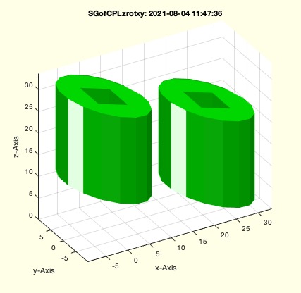
Syntax
SG=SGofCPLzrotxy(CPL,[z,w])
Input Parameter
CPL: | | CPL |
z: | | height |
w: | | roatation angle in [x y z] |
Output Parameter
Examples
SGofCPLzrotxy (PLsquare([20 40]),50,[0 pi/10 0])
SGofCPLzrotxy (PLsquare([20 40]),50,[0 pi/10 pi/4])
SGofCPLzrotxy (CPLsample(12),50,[0 pi/10])
Copyright 2021-2025 Tim C. Lueth. All rights reserved. The code is the property of Tim C. Lueth and may not be redistributed or modified without explicit written permission. This software may be used free of charge for academic research and teaching purposes only. Commercial use, redistribution, modification, or reverse engineering is strictly prohibited. Access to source code is restricted and granted only under specific agreements. For licensing inquiries or commercial use, please contact: Tim C. Lueth
Algorithm (Workflow)
This function, SGofCPLzrotxy, is designed to rotate a closed polyline (CPL) and extrude it along the z-axis. It is part of the SolidGeometry library and was introduced in version 5.1. The function takes a CPL and optional parameters for height and rotation angles, and outputs a solid geometry (SG).
Input Parameters
- CPL: The closed polyline to be rotated and extruded.
- z: The height for extrusion. If a single value is provided, it is converted to a two-element vector [0, z].
- w: A vector specifying rotation angles in the x, y, and z directions. Default is [0, 0, 0].
Output
- SG: The resulting solid geometry after rotation and extrusion.
Algorithm Steps
- Retrieve the height parameter
z from varargin. If z is a single value, convert it to a two-element vector [0, z].
- Retrieve the rotation angles
w from varargin, defaulting to [0, 0, 0] if not provided.
- Convert the CPL to a polyline using
PLofCPL.
- Transform the polyline by adding a z-coordinate of 0 and applying a rotation in the x and y directions using
VLtransR and rot functions.
- Normalize the z-coordinates by subtracting the minimum z-value from all z-coordinates.
- Generate a 2D Delaunay triangulation of the transformed polyline to obtain points and faces.
- Determine the border edges of the faces using
ELofFLborder.
- Extrude the 2D triangulation along the z-axis using
VLFLofPLELz to create a 3D solid.
- Adjust the z-coordinates of the vertices to match the original polyline's z-coordinates, offset by the extrusion height.
- Store the adjusted vertices and faces in the output solid geometry
SG.
- Translate the solid geometry along the z-axis by
z(1) using SGtransP.
- Rotate the solid geometry around the z-axis by
w(3) using SGrotate.
- If no output is requested, plot the solid geometry using
SGfigure and SGplotalpha.
Algorithm explaination created using ChatGPT on 2025-08-18 18:53. (Please note: No guarantee for the correctness of this explanation)
Last html export of this page out of FM database by TL: 2025-09-21