by Tim C. Lueth, SG-Lib Toolbox: SolidGeometry 5.6 - Parametric Design
Introduced first in SolidGeometry 5.1, Creation date: 2021-03-07, Last change: 2025-09-15
[A,SL_F]=SGsblink([L,sdl,hex,fit,rod])
L: | [L level-F Level-B]; Distance and level [-n .. 0 .. n]; default is [50 1 0] | |
sdl: | [Di Do b] Inner D, Outer D and width of Bearing; default [6 13 5] | |
hex: | optional diameter of an inner hexagon in the shaft | |
fit: | if true, the pin use slfit('b') and will interfere; default is false | |
rod: | a rod is created instead of a link; use true or ez vectors |
A: | Geometry of the Link | |
SL_F: | SLEEVE if abs(level)>1 for Pin 1 |
SGfigure; fourBarLinkageplotanim([110,70,90,50]);
SGsblink([50 -2],[6 13 5],3)
SGsblink([50 -2],[6 13 5],3,true)
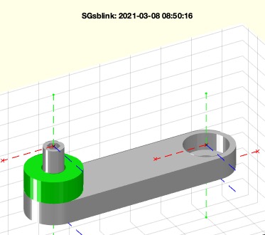
SGsblink([50 1 -1]);
SGsblink([50 0 0]);
SGsblink([50 1],[6 13 5],3,'',true) % creates a rod
SGsblink([20 0 0],[6 13 5 2.5],'','',[1 0 1]); B=ans
SGsblink([10 1 0],[6 13 5 2.7],'','',true); B=ans
SGsblink([20 0 0],[6 13 5 2.7],'','',[1 0 1; -1 0 1]); B=ans
SGsblink([20 1 1],[6 13 5 2.7],[5 -1],'',[1 0 1; -1 0 1]); B=ans
SGsblink([20 1 0],[6 13 5 2.7],[5 -1],'',[1 0 1; -1 0 1]); B=ans