VLFLshaft
by Tim C. Lueth, SG-Lib Toolbox: SolidGeometry 5.6 - Modeling function
Introduced first in SolidGeometry 1.1, Creation date: 2013-07-13, Last change: 2025-09-14
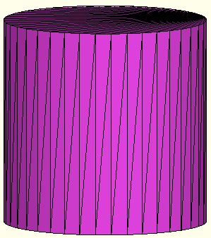
returns VL and FL of a solid axle
Description
This function is described in chapter 2 of the article collection of Tim Lueth and Franz Irlinger on the automatic construction of 3D printable mechanisms
See Also: VLFLsnapfit
, VLFLhollowsnapaxle
, VLFLcat
, TofDPhiH
, VLtransT
, VLFLspacer
, VLFLbolt
, VLFLlinkage
, VLFLwriteSTL
, VLFLofPLELz
, VLFLplot
Example Illustration
Syntax
[VL,FL]=VLFLshaft(R,h,n)
Input Parameter
R: | | Radius |
h: | | Height |
n: | | number of edges |
Output Parameter
VL: | | Vertex list |
FL: | | Facet list |
Copyright 2013-2025 Tim C. Lueth. All rights reserved. The code is the property of Tim C. Lueth and may not be redistributed or modified without explicit written permission. This software may be used free of charge for academic research and teaching purposes only. Commercial use, redistribution, modification, or reverse engineering is strictly prohibited. Access to source code is restricted and granted only under specific agreements. For licensing inquiries or commercial use, please contact: Tim C. Lueth
Algorithm (Workflow)
This function, VLFLshaft, generates a 3D model of a solid axle by computing its vertex and facet lists. It is part of the SG-Library and was developed by Tim Lueth.
Input Parameters
- R: Radius of the axle.
- h: Height of the axle.
- n: Number of edges for the polygonal base and top of the axle.
Output Results
- VL: Vertex list, which contains the coordinates of the vertices of the axle.
- FL: Facet list, which defines the triangular facets that make up the surface of the axle.
Algorithm Steps
- Call
PLcircle(R, n) to generate a list of points PL that form a circle with radius R and n edges.
- Define the z-coordinates for the base (
z0) and top (z1) of the axle as 0 and h, respectively.
- Create the upper vertex list
VLU by appending z0 to each point in PL.
- Create the lower vertex list
VLO by appending z1 to each point in PL.
- Define the facets
FL for a convex polygon using the indices of the vertices.
- Adjust the orientation of the facets for the base plate to create
FLU.
- Correct the vertex indices for the cover plate to create
FLO.
- Define the wall facets
FLW by connecting the vertices of the base and top plates.
- Reshape and reorder
FLW to ensure correct facet orientation.
- Combine
VLU and VLO to form the complete vertex list VL.
- Combine
FLU, FLO, and FLW to form the complete facet list FL.
Algorithm explaination created using ChatGPT on 2025-08-19 01:09. (Please note: No guarantee for the correctness of this explanation)
Last html export of this page out of FM database by TL: 2025-09-21