VLFLthreadnut
by Marie L. Lueth, SG-Lib Toolbox: SolidGeometry 5.6 - SG/Solids
Introduced first in SolidGeometry 1.0, Creation date: 2012-12-27, Last change: 2025-09-14
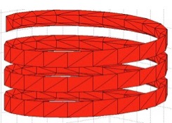
generates a screw nut's thread
Example Illustration
Syntax
[VL,FL]=VLFLthreadnut(H,D,d,di,h,[alpha])
Input Parameter
H: | | Height of the thread |
D: | | Outer diameter |
d: | | Core diameter |
di: | | Inner diameter |
h: | | Thread pitch |
alpha: | | Thread angle; default is pi/3 (60 Degree) |
Output Parameter
VL: | | Vertex list |
FL: | | Facet list |
Examples
Generating the thread of a DIN 13 M8 nut with 5mm height.
[VL,FL]=VLFLthreadnut (5,8,6.65,7.33,1.25);
VLFLplot (VL,FL); axis equal;
Copyright 2012-2025 Tim C. Lueth. All rights reserved. The code is the property of Tim C. Lueth and may not be redistributed or modified without explicit written permission. This software may be used free of charge for academic research and teaching purposes only. Commercial use, redistribution, modification, or reverse engineering is strictly prohibited. Access to source code is restricted and granted only under specific agreements. For licensing inquiries or commercial use, please contact: Tim C. Lueth
Algorithm (Workflow)
This algorithm generates the 3D model of a screw nut's thread. It takes several input parameters to define the geometry of the thread and outputs a vertex list and a facet list for 3D rendering.
Input Parameters
- H: Height of the thread.
- D: Outer diameter of the thread.
- d: Core diameter of the thread.
- di: Inner diameter of the thread.
- h: Thread pitch, which is the distance between threads.
- alpha (optional): Thread angle, default is pi/3 (60 degrees).
Output Results
- VL: Vertex list, which contains the coordinates of the vertices of the thread model.
- FL: Facet list, which defines the triangular facets of the thread model using the vertex indices.
Algorithm Steps
- Set the default thread angle
alpha to pi/3 if not provided.
- Calculate the radii:
R (outer), r (core), and ri (inner).
- Compute
tana2 as the tangent of half the thread angle.
- Calculate
r0, the effective radius for the thread profile.
- Determine the thread profile parameters
u, t, U, and S.
- Calculate the number of radial divisions
n using the function nofrd with a tolerance of 0.05.
- Adjust the height
H by subtracting U and calculate the number of thread turns L.
- Create a vertical coordinate array
z for the thread height.
- Generate angular coordinates
w for the thread turns.
- Compute the 3D coordinates for the outer, inner, and core profiles of the thread using trigonometric functions.
- Assemble the profiles into a single point list
PL and transpose it to form the vertex list VL.
- Define the facet lists
FL1, FL2, FL3, and FL4 for the thread surfaces.
- Include additional facets
FLs for the thread ends.
- Combine all facet lists into a single facet list
FL.
Algorithm explaination created using ChatGPT on 2025-08-19 07:37. (Please note: No guarantee for the correctness of this explanation)
Last html export of this page out of FM database by TL: 2025-09-21