by Tim C. Lueth, SG-Lib Toolbox: SolidGeometry 5.6 - Serial-Robotics
Introduced first in SolidGeometry 5.4, Creation date: 2024-08-11, Last change: 2025-08-19
See Also: SGraamboTCPmagnetpull
, SGgearwheelsocketspanner
, SGraamboTCPbagcutter
, SGraamboTCPMagnetM22
, SGraamboTCPknurledgearcover
, SGraamboTCPgearwheeldisk
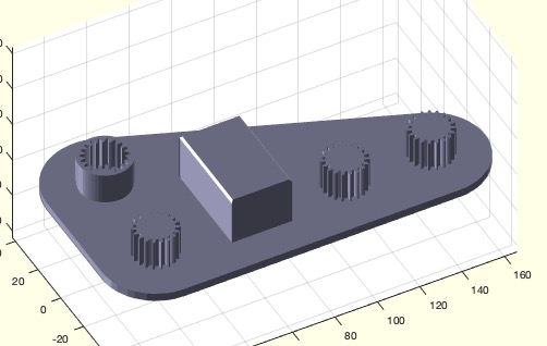
SGall=SGraamboTCPtoolstand
SGall: | Final solid for the desktop |
SGraamboTCPtoolstandThis MATLAB function, SGraamboTCPtoolstand, is designed to create a tool stand for a designer's desktop. It is part of the SolidGeometry library and was introduced in version 5.4. The function returns a solid geometry object, SGall, which represents the final tool stand.
varargin: A variable-length input argument list that allows the function to accept optional parameters.getfuncparamStr function. This determines if the output should be saved as an STL file.SGgearDINrot function:
SGG: A gear with positive rotation, module 1, 19 teeth, and a height of 15 mm.SGI: A gear with negative rotation, module 1, 19 teeth, a circular profile with a diameter of 24.8 mm, and a height of 15 mm.SGM, is created using the SGtransP and SGtrans0 functions. It is based on a chamfered square profile with dimensions 46.5 mm by 28.5 mm and a chamfer of 24 mm. The model is then rotated by -90 degrees around the z-axis using SGrotate.SGarrangeSG:
SGR1: Contains the motor model and three gears, arranged with a maximum size of 240 mm by 240 mm.SGR2: Contains the inverted gear model.SGtransrelSG to place SGR1 in front of SGR2.SGN, is created under SGR1 using SGplateunder with a thickness of 4 mm and a height of 15 mm.SGall, is created by concatenating SGR1 and SGN using SGconcat.SGfigure and SGplotalpha. If the 'STL' parameter is present, the tool stand is saved as an STL file using SGwriteMultipleSTL.