by Tim C. Lueth, SG-Lib Toolbox: SolidGeometry 5.6 - SimMechanics
Introduced first in SolidGeometry 3.0, Creation date: 2016-11-10, Last change: 2025-09-14
h=smbAddLine(P1,P2)
P1: | Name of Port 1 | |
P2: | Name of Port 2 |
h: | handle to Line |
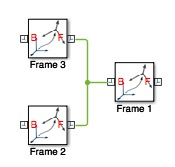
Create two Rigid Tranformation and draw a line:
smbAddFrame('Frame 1');smbAddFrame('Frame 2');smbAddFrame('Frame 3');
smbAddLine('Frame 1/LConn1','Frame 2/Rconn1')
smbAddLine('Frame 1/LConn1','Frame 3/Rconn1')
This function, smbAddLine, is part of the SimMechanics library and is used to create a line between two block ports in a Simulink model. The function is designed to work within the context of a Simulink model, specifically using the current system as the target for adding the line.
The function begins by determining the current system in Simulink using the gcs function, which stands for "get current system." This function returns the name of the currently active Simulink system, which is stored in the variable FSys.
Next, the function calls add_line, a built-in Simulink function, with three arguments: FSys, P1, and P2. The add_line function creates a line between the specified ports P1 and P2 within the current system FSys.
The handle to the newly created line is returned as the output h.
The example provided in the comments demonstrates how to use the function to create lines between ports of different frames:
smbAddFrame('Frame 1');
smbAddFrame('Frame 2');
smbAddFrame('Frame 3');
smbAddLine('Frame 1/LConn1', 'Frame 2/Rconn1');
smbAddLine('Frame 1/LConn1', 'Frame 3/Rconn1');
In this example, three frames are created, and lines are drawn between the specified ports of these frames.
Algorithm explaination created using ChatGPT on 2025-08-18 23:18. (Please note: No guarantee for the correctness of this explanation)