Posefourbaranglelimit
by Tim C. Lueth, SG-Lib Toolbox: SolidGeometry 5.6 - 4Bar/Linkages
Introduced first in SolidGeometry 4.7, Creation date: 2019-07-03, Last change: 2025-09-14
limits the angle are of a specific fourbar solution
See Also: Posefourbarangles
, Posefourbarposelimit
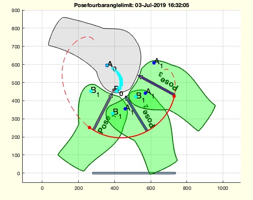
Example Illustration
Syntax
PS=Posefourbaranglelimit(PS,aps,ival)
Input Parameter
PS: | | Pose struct including PS.GAL |
aps: | | number of attachment point solution |
ival: | | [min max] angle of the crank |
Output Parameter
PS: | | Pose struct with modified PS.GAL angle interval |
Examples
PS=Posesample(19)
PS=checkfourbar3Poseattachpermutation(PS,'',10)
SGfigure; Poseplot(PS); Poseplotspace(PS)
Posefourbaranglelimit(PS,759,[290 7]/180*pi)
Posefourbarplot(PS,759)
Copyright 2019-2025 Tim C. Lueth. All rights reserved. The code is the property of Tim C. Lueth and may not be redistributed or modified without explicit written permission. This software may be used free of charge for academic research and teaching purposes only. Commercial use, redistribution, modification, or reverse engineering is strictly prohibited. Access to source code is restricted and granted only under specific agreements. For licensing inquiries or commercial use, please contact: Tim C. Lueth
Algorithm (Workflow)
This function, Posefourbaranglelimit, is designed to limit the angle area of a specific four-bar linkage solution. It modifies the angle interval of a given pose structure.
Input Parameters
- PS: A pose structure that includes the field
PS.GAL.
- aps: An integer representing the number of the attachment point solution.
- ival: A two-element vector specifying the minimum and maximum angles of the crank in radians.
Output
- PS: The modified pose structure with an updated
PS.GAL angle interval.
Algorithm Steps
- Store the original pose structure
PS in PSO.
- Normalize the angle interval
ival to be within the range of 0 to 2À using the modulus operation.
- If the second element of
ival is less than the first, adjust it by adding 2À to ensure a valid interval.
- Update the
PS.GAL field for the specified attachment point solution aps with the new angle interval ival.
- If no output is requested (i.e.,
nargout == 0), perform the following visualization steps:
- Call
SGfigure to create a new figure.
- Plot the original and modified pose using
Poseplot and Poseplotspace.
- Calculate the coupler curve for the original pose
PSO and the modified pose PS using PLofPosecouplercurve.
- Plot the original coupler curve in red dashed lines and the modified coupler curve in solid red lines with a line width of 2 using
PLplot.
- Highlight the start and end points of the modified coupler curve with red asterisks using
PLplot.
Algorithm explaination created using ChatGPT on 2025-08-18 23:48. (Please note: No guarantee for the correctness of this explanation)
Last html export of this page out of FM database by TL: 2025-09-21