SGofR12
by Tim C. Lueth, SG-Lib Toolbox: SolidGeometry 5.6 - Kinematics and Frames
Introduced first in SolidGeometry 5.1, Creation date: 2022-02-07, Last change: 2025-09-15
creates a solid to show the minimal solid size for assembly methods
See Also: SGofR12
, R12ofM
, plotannotationSG
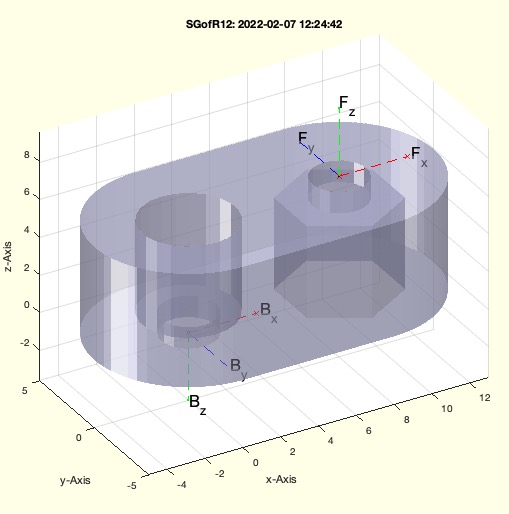
Example Illustration
Syntax
[SG,RMHL]=SGofR12([R12,DIN])
Input Parameter
R12: | | Dimensions of a link |
DIN: | | if true; the function SGdesignDIN912DIN985is used; default is false |
Output Parameter
SG: | | Solid of this link |
RMHL: | | Minimal Dimensions |
Examples
SGofR12([5 2.5 4])
SGofR12([5 2.5 4],true)
Copyright 2022-2025 Tim C. Lueth. All rights reserved. The code is the property of Tim C. Lueth and may not be redistributed or modified without explicit written permission. This software may be used free of charge for academic research and teaching purposes only. Commercial use, redistribution, modification, or reverse engineering is strictly prohibited. Access to source code is restricted and granted only under specific agreements. For licensing inquiries or commercial use, please contact: Tim C. Lueth
Algorithm (Workflow)
This function, SGofR12, is designed to create a solid representation of a link with minimal dimensions for assembly methods. It is part of the SolidGeometry library and was introduced in version 5.1.
Input Parameters
- R12: A vector containing the dimensions of a link. Default values are [6, 2.5, 6].
- DIN: A boolean indicating whether to use the SGdesignDIN912DIN985 function. Default is false.
Output Results
- SG: The solid representation of the link.
- RMHL: A vector containing the minimal dimensions [Rmin, M, Hmin, Lmin].
Algorithm Steps
- Retrieve the R12 and DIN parameters using the getfuncparams function. Default values are used if not provided.
- Extract the individual dimensions Ro, M, and H from the R12 vector.
- Calculate the initial length L as 1.5 times Ro.
- Set a minimum wall thickness of 1.25 mm.
- Use the DIN985 function to adjust the M dimension and obtain the TL vector.
- Calculate the minimal radius Rmin, length Lmin, and height Hmin based on TL and wallmin.
- Update the RMHL vector with the calculated minimal dimensions.
- Ensure Ro, L, and H are at least as large as their respective minimal values.
- Create a profile PL using the PLcircleoval function with Ro and L.
- Generate the solid SG using the SGofCPLz function with PL and H.
- Set the bottom and front transformations of SG using the SGTset function.
- If DIN is true, use the SGdesignDIN912DIN985 function to design the solid H, N, and S. Otherwise, create a cylinder N with SGcylinder and set its transformation.
- Subtract H and N from SG using the SGsubtract function with alignment options.
- If no output is requested, plot the solid SG using SGfigure and SGTplotalpha functions.
Algorithm explaination created using ChatGPT on 2025-08-19 07:51. (Please note: No guarantee for the correctness of this explanation)
Last html export of this page out of FM database by TL: 2025-09-21