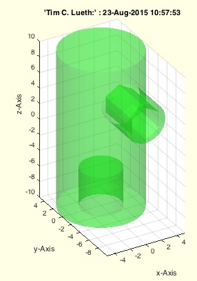
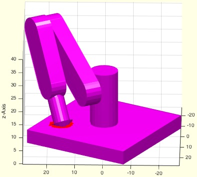
SGweight(SG,sw,res)- returns the estimated weight of a solid |
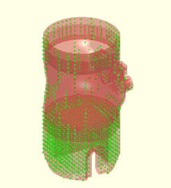 | % SGweight(SG,sw,res) - returns the estimated weight of a solid % (by Tim Lueth, VLFL-Lib, 2015-AUG-26 as class: MECHANICAL PROCEDURES) % % Calculated by counting the volume elements that are included by the % solid body. % Faster than slicing using SGweight, SGvolume, SGisInterior, VMofSG % (Status of: 2019-07-28) % % Introduced first in SolidGeometry 2.4 % % See also: SGweight, SGvolume, SGisInterior, VMofSG % % [W,VM,nd]=SGweight(SG,[sw,res]) % === INPUT PARAMETERS === % SG: Solid Geoemtry % sw: specific weight; default is 1.15g/cm^3 (Nylon) % res: resolution; default is 2x2x2 mm^3 % === OUTPUT RESULTS ====== % W: Estimated weight in gramm % VM: Logical Voxel model % nd: dimensions of VM, same as size(VM) % % EXAMPLE: % loadweb JACO_robot.mat % [W,VM,nd]=SGweight(JC0,'',2); W % SGfigure; VMplot(VM*2000) % % % See also: SGweight, SGvolume, SGisInterior, VMofSG % % % Copyright 2015-2019 Tim C. Lueth |
TofSGMLez(SG,ez,ai,fe)- returns HT for a mounting face with known ez |
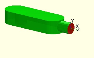 | % TofSGMLez(SG,ez,ai,fe) - returns HT for a mounting face with known ez % (by Tim Lueth, VLFL-Lib, 2015-AUG-24 as class: ANALYTICAL GEOMETRY) % % % Similar to TofSGML but here, the faces are seleted by the ez-vector % (Status of: 2017-04-18) % % Introduced first in SolidGeometry 2.4 % % See also: TofSGMLez, TofSGML, TofVLUL, TofVLULez, MLofSG, MLplot % % T=TofSGMLez(SG,ez,[ai,fe]) % === INPUT PARAMETERS === % SG: Solid Geometry with defined mounting faces ML, MA % ez: desired ez vector % ai: order is size; default is 1 % fe: feature edge angle; default is 0.5; used only if ML is not defined % === OUTPUT RESULTS ====== % T: Transformation matrix [4x4] % % EXAMPLE: % load AIM_SGrobot % TofSGMLez(SG3,[1 0 0]); % % See also: TofSGMLez, TofSGML, TofVLUL, TofVLULez, MLofSG, MLplot % % % Copyright 2015-2017 Tim C. Lueth |
TofSGML(SG,mi,fe)- returns HT for a mounting face with known number |
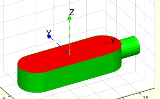 | % TofSGML(SG,mi,fe) - returns HT for a mounting face with known number % (by Tim Lueth, VLFL-Lib, 2015-AUG-24 as class: ANALYTICAL GEOMETRY) % % % Similar to TofSGMLez but here, the faces are seleted by the number % (Status of: 2017-04-18) % % Introduced first in SolidGeometry 2.4 % % See also: TofSGMLez, TofVLUL, TofVLULez, MLofSG, MLplot % % [T,SG]=TofSGML(SG,mi,[fe]) % === INPUT PARAMETERS === % SG: Solid Geometry with defined mounting faces ML, MA % mi: mounting face number % fe: feature edge angle; default is 0.5; used only if ML is not defined % === OUTPUT RESULTS ====== % T: Transformation matrix [4x4] % SG: Solid geometry with defined mounting faces ML, MA % % EXAMPLE: % load AIM_SGrobot % TofSGML(SG3,2); % % See also: TofSGMLez, TofVLUL, TofVLULez, MLofSG, MLplot % % % Copyright 2015-2017 Tim C. Lueth |
MLplot(SG,mi,fe)- plots the mounting faces of a solid |
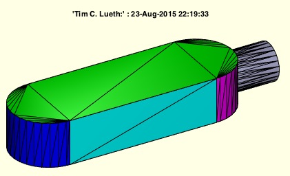 | % MLplot(SG,mi,fe) - plots the mounting faces of a solid % (by Tim Lueth, VLFL-Lib, 2015-AUG-23 as class: SURFACES) % % calculates using MFofSG, if not existing already, the mounting faces % and plots them in different colors (Status of: 2017-01-29) % % Introduced first in SolidGeometry 2.4 % % See also: TofSGMLez, TofSGML, TofSGMLez, MLofSG, SGplatesofSGML % % h=MLplot(SG,[mi,fe]) % === INPUT PARAMETERS === % SG: Solid Geoemtry % mi: mounting face index; default is '' % fe: feature angle; default is 0.5 % === OUTPUT RESULTS ====== % h: handle % % EXAMPLE: % [~,~,SG]=MLofSG(SGsample(5)); MLplot(SG) % % See also: TofSGMLez, TofSGML, TofSGMLez, MLofSG, SGplatesofSGML % % % Copyright 2015-2017 Tim C. Lueth |
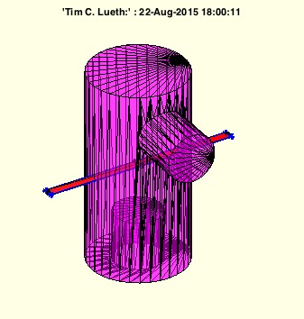
exp_2015_08_22- EXPERIMENT to show simple impression of objects in planes |
 | %% PUBLISHABLE EXP_2015_08_22 EXPERIMENT TO SHOW SIMPLE IMPRESSION OF OBJECTS IN PLANES % (by Tim Lueth, VLFL-Lib, 2015-AUG-22 as class: EXPERIMENTS) %% % exp_2015_08_22 - EXPERIMENT to show simple impression of objects in % planes % (by Tim Lueth, VLFL-Lib, 2015-AUG-22 as class: EXPERIMENTS) % % exp_2015_08_22 % |
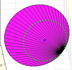
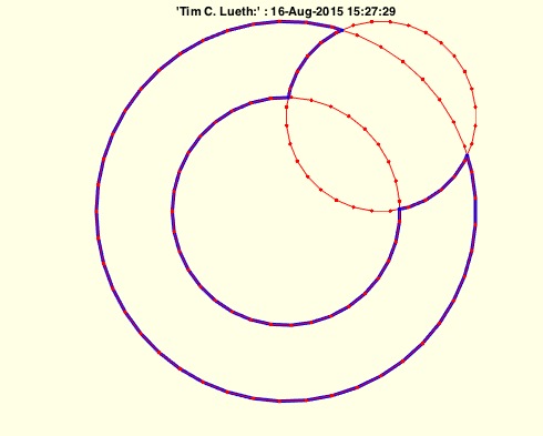
tangentRP(R,p,pc)- returns the two tangential points of a circle |
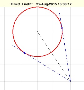 | % tangentRP(R,p,pc) - returns the two tangential points of a circle % (by MATLAB-CENTRAL, VLFL-Lib, 2015-AUG-22 as class: ANALYTICAL GEOMETRY) % % Thanks to Laurens de Smedt for finding it at MATLAB-Central % (Status of: 2018-08-05) % % See also: center3P, center4P, tangente, tangenteRP % % [q1,q2,w1,w2]=tangentRP(R,p,[pc]) % === INPUT PARAMETERS === % R: Radius of the circle % p: point to match % pc: optional center of the circle; default is [0 0] % === OUTPUT RESULTS ====== % q1: point 1 (green) % q2: point 1 (magenta) % w1: angle of q1 in world coordinates relative to pc % w2: angle of q2 in world coordinates relative to pc % % EXAMPLE: tangentRP(10,[20 20]) % % See also: center3P, center4P, tangente, tangenteRP % |
PLFLofVLELdelaunay(VL,EL)- closes a planar surface of VLEL by delaunay |
 | % PLFLofVLELdelaunay(VL,EL) - closes a planar surface of VLEL by delaunay % (by Tim Lueth, VLFL-Lib, 2015-AUG-21 as class: SURFACES) % % This fnctn could be named also as FLofVLELdelaunay(VL,EL). In contrast % to FLofPLEL it uses delaunayTriangulation insteadt of the outdated % DelaunayTri (Status of: 2017-08-23) % % Introduced first in SolidGeometry 2.4 % % See also: FLofPLEL % % [PL,FL,EL]=PLFLofVLELdelaunay(VL,EL) % === INPUT PARAMETERS === % VL: Vertex list [nx3] % EL: Edge consraints % === OUTPUT RESULTS ====== % PL: Point List % FL: Tesselated facet list % EL: Same Edge List % % See also: FLofPLEL % % % Copyright 2015-2017 Tim C. Lueth |
PLofVLFL(VL,FL,fi)- returns the 2D representation for a planar VLFL |
 | % PLofVLFL(VL,FL,fi) - returns the 2D representation for a planar VLFL % (by Tim Lueth, VLFL-Lib, 2015-AUG-20 as class: SURFACES) % % This procedure analyzes generates a HT-Matrix by the first point of the % first facet, the ez-vector of the surface, and the longest distance to % another point of the facets as ex-axis. (Status of: 2015-08-20) % % [PL,T,c,d]=PLofVLFL(VL,FL,[fi]) % === INPUT PARAMETERS === % VL: Vertex list [nx3] % FL: Facet list of a planar surface [nx3] % fi: selected indices; default is all % === OUTPUT RESULTS ====== % PL: Point list [nx2] % T: Transformation matrix % c: index list to transform PL indices into VL indices % d: index list to transform VL indices into PL indices % % EXAMPLE: FL=FLofn(50); % VL=VLtrans(PLcircle(10,50),rotdeg(20,30,40)); % PLofVLFL(VL,FL(30:40,:)); % [PL,T,c,d]=PLofVLFL(VL,FL(30:40,:)); c, d(FL(30:40,:)) % |
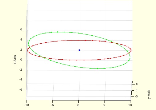
vertexNormalbyFN(TR3)- calculates the vertex normals based on the facet normals |
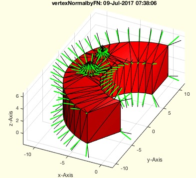 | % vertexNormalbyFN(TR3) - calculates the vertex normals based on the facet normals % (by Tim Lueth, VLFL-Lib, 2015-AUG-21 as class: SURFACES) % % This fnctn is sometimes required to improve the result of MATLAB's % vertexNormal fnctn. It is about 40 times slower (Status of: 2017-07-08) % % Introduced first in SolidGeometry 2.4 % % See also: vertexNormal % % [NNL,NL]=vertexNormalbyFN(TR3) % === INPUT PARAMETERS === % TR3: triangulation % === OUTPUT RESULTS ====== % NNL: Normal vector list % NL: vector sum of the face norms attached to the vertex % % EXAMPLE: % vertexNormalbyFN(SGbox([30,20,10])) % vertexNormalbyFN(SGsample(25)) % % See also: vertexNormal % |
incenterVLFL(VL,FL)- returns the center of a surface and of all facets |
 | % incenterVLFL(VL,FL) - returns the center of a surface and of all facets % (by Tim Lueth, VLFL-Lib, 2015-AUG-21 as class: SURFACES) % % [CVL,SCV]=incenterVLFL(VL,FL) % === INPUT PARAMETERS === % VL: Vertex list [nx2] or [nx3] % FL: Facet list % === OUTPUT RESULTS ====== % CVL: Center Vertex List % SCV: Surface Center Vertex % |
PLofVL(VL)- Converts a planer VL[nx3] into a PL [nx2] |
 | % PLofVL(VL) - Converts a planer VL[nx3] into a PL [nx2] % (by Tim Lueth, VLFL-Lib, 2015-AUG-21 as class: AUXILIARY PROCEDURES) % % IN SG-LIB 5.0 we have to following concepts: % - (2010) - T3P: T - right hand system from 3 Point. Origin is p1 % - (2012) - TofVL: T - Eigenvalues and Center of convexhull of VL % - (2015) - PLofVL: T - ex is the longest distance of mean(VL) % - (2016) - TofPez: T - ey has no x dimension or ex=[0 0 1] % - (2019) - TofVLFL:T - ez is calucated from the face normals, o=mean(VL) % - (2020) - VLeigenvect - same as TofVL but no convex hull and faster % - (2020) - TofCVL: T - ez is calucated from the edge normals, o=mean(VL) % (Status of: 2020-09-14) % % Introduced first in SolidGeometry 2.4 % % See also: TofVLFL, VLeigenvect, TofVL, T3P, TofPez, TofCVL % % [PL,T]=PLofVL(VL) % === INPUT PARAMETERS === % VL: Vertex list [nx3] % === OUTPUT RESULTS ====== % PL: Point list [nx2] % T: Transformation matrix for transformation PL->VL % % EXAMPLE: % PLofVL(VLtrans(PLcircle(10,13,[],8),rotdeg(90,90,90))); % % See also: TofVLFL, VLeigenvect, TofVL, T3P, TofPez, TofCVL % % % Copyright 2015-2020 Tim C. Lueth |
exp_2015_08_20b (SG,k)- EXPERIMENT just for testing retesselation by ULofSG |
 | % exp_2015_08_20b (SG,k) - EXPERIMENT just for testing retesselation by % ULofSG % (by Tim Lueth, VLFL-Lib, 2015-AUG-20 as class: EXPERIMENTS) % % exp_2015_08_20b(SG,k) % === INPUT PARAMETERS === % SG: Solid Geometry % k: index for surface retesselation % % EXAMPLE: load AIM_SGrobot % exp_2015_08_20c(SG1) % |
exp_2015_08_20c(SG,k)- EXPERIMENT just for retesselation by ULofSG |
 | % exp_2015_08_20c(SG,k) - EXPERIMENT just for retesselation by ULofSG % (by Tim Lueth, VLFL-Lib, 2015-AUG-20 as class: EXPERIMENTS) % % NSG=exp_2015_08_20c(SG,k) % === INPUT PARAMETERS === % SG: Solid Geometry % k: index for surface retesselation % === OUTPUT RESULTS ====== % NSG: New Solid % % EXAMPLE: load AIM_SGrobot % exp_2015_08_20c(SG1) % |
SGcontourtube(CPL,VL,VLO)- extrudes a CPL along a path given as CVL |
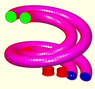 | % SGcontourtube(CPL,VL,VLO) - extrudes a CPL along a path given as CVL % (by Tim Lueth, VLFL-Lib, 2015-AUG-19 as class: SURFACES) % % ======================================================================= % OBSOLETE (2018-08-17) - USE 'SGofCPLtransT' INSTEAD % ======================================================================= % % Powerful procedure to extrude PLs [nx2] anlog a path (Status of: % 2018-08-17) % % Introduced first in SolidGeometry 2.4 % % See also: [ SGofCPLtransT ] ; TLofCVL, SGofCPLCVLR, SGcontourtube2, % SGofCPLtransT, SGof2T, SGof2SGT, RLofEulerInterpolation, % VLinsertEulerSteps, VLradialEdges, TofPez % % [SG,FLS,FLE,FLW,TS,TE]=SGcontourtube(CPL,VL,VLO) % === INPUT PARAMETERS === % CPL: Closed point list [nx2] % VL: Vertex list [nx3] % VLO: Second vertex list [nx3] % === OUTPUT RESULTS ====== % SG: Solid geometry % FLS: FL of starting surface % FLE: FL of ending surface % FLW: FL of the wall % TS: Starting Frame % TE: End Frame % % EXAMPLE: % VL=VLhelix(40,100,3*pi); VLO=[VL(:,1:2)*1.1 VL(:,3)]; % SGcontourtube(PLcircle(10),VL,VLO) % % See also: [ SGofCPLtransT ] ; TLofCVL, SGofCPLCVLR, SGcontourtube2, % SGofCPLtransT, SGof2T, SGof2SGT, RLofEulerInterpolation, % VLinsertEulerSteps, VLradialEdges, TofPez % % % Copyright 2015-2018 Tim C. Lueth |
VLtransN(VLO,FLO,s,d)- returns a relative to normal vectors transformed vertex list |
 | % VLtransN(VLO,FLO,s,d) - returns a relative to normal vectors transformed vertex list % (by Tim Lueth, VLFL-Lib, 2015-AUG-19 as class: SURFACES) % % See also: VLtransT, VLtransP, VLtrans1, VLtrans0, VLtransR, VLtransT, % VLtrans % % [VL,EL,EOL,FL,VNL]=VLtransN(VLO,FLO,[s,d]) % === INPUT PARAMETERS === % VLO: Vertex list of a planar surface % FLO: Facet list of a planar surface % s: shrink factor % d: distance factor % === OUTPUT RESULTS ====== % VL: Vertex list [nx3] % EL: Edge list [nx2] % EOL: Edge orthogonal list [nx3] % FL: Facet list [nx3] % VNL: Vertex normal list [nx3] % |
exp_2015_08_20 (SG)- EXPERIMENT to connect two surfaces by a small tube |
 | % exp_2015_08_20 (SG) - EXPERIMENT to connect two surfaces by a small tube % (by Tim Lueth, VLFL-Lib, 2015-AUG-19 as class: EXPERIMENTS) % % exp_2015_08_20(SG) % === INPUT PARAMETERS === % SG: % % EXAMPLE: load AIM_SGrobot % exp_2015_08_20(SG1) % |
MLofSG(SG,fi,fe,amin)- calculates of the mounting face list of the solid |
 | % MLofSG(SG,fi,fe,amin) - calculates of the mounting face list of the solid % (by Tim Lueth, VLFL-Lib, 2015-AUG-19 as class: SURFACES) % % MLofSG uses TR3mountingfaces to calculate the desired union faces. % Therefore, it is able to handel spherical faces too. If only planar % faces are allowed (i.e. fe=0) , the fnctn is up to 10 to 25 times % faster. The slower plotting if nargout=0 by drawnow slows down but % allows user interruption! % ML contains for all faces of FL, the index of the mounting face % The first column of MA contains the mounting face index Ai(:,1) % The second column of MA contains the area of the union surface Ai(:,2) % the 3rd-5th column of MA contains the normal vector length Ai(:,3:5). % The normal vector was calculated by the sum of all normal vectors % divided by the number of faces, therefor for spherical mounting faces, % the norm of Ai(i, 3:5) is not 1 but smaller. Use % [a,b]=VLnorm(MA(:,3:5)) to find the non planar surfaces. In this case b % is smaller than 0. % (Status of: 2017-01-29) % % Introduced first in SolidGeometry 2.4 % % See also: TofSGMLez, TofSGML, TofSGMLez, MLplot, SGplatesofSGML % % [ML,MA,SG]=MLofSG(SG,[fi,fe,amin]) % === INPUT PARAMETERS === % SG: Solid Geometry % fi: facet index or empty % fe: feature edge angle (0.3) is default % amin: minimal facet are to consider as start point;default is 0 % === OUTPUT RESULTS ====== % ML: Mounting face index list of FL (nx1), n=length(FL) % MA: Array [nx5]= [mounting area index(1) area (1) normal vector(3)] % SG: SG.ML und SG.MA added using ML and MA if fi=[]; % % EXAMPLE: load AIM_SGrobot; % SG=SG1, fe=0.5, MLofSG(SG,[],fe); % [ML,MA]=MLofSG(SG,[],fe), MA(:,[1 3 4 5]), [a,b]=VLnorm(MA(:,3:5)) % SG.FL(ML==4,:), % return the facets that belong to union 4 % SG.FL(ML~=4,:), % return the facets that do not belong to union 4 % % See also: TofSGMLez, TofSGML, TofSGMLez, MLplot, SGplatesofSGML % % % Copyright 2015-2017 Tim C. Lueth |
exp_2015_08_19(A,B,oct)- EXPERIMENT that shows an octree separation |
 | % exp_2015_08_19(A,B,oct) - EXPERIMENT that shows an octree separation % (by Tim Lueth, VLFL-Lib, 2015-AUG-19 as class: EXPERIMENTS) % % exp_2015_08_19(A,B,[oct]) % === INPUT PARAMETERS === % A: Solid A % B: Solid B % oct: octree size ([oct x oct x oct]); default is 40 % % EXAMPLE: % exp_2015_08_19([],[]) % |
CPLunite(CPL,ord)- returns a CPL that has no crossing lines anymore |
 | % CPLunite(CPL,ord) - returns a CPL that has no crossing lines anymore % (by Tim Lueth, VLFL-Lib, 2015-AUG-16 as class: CLOSED POLYGON LISTS) % % By analyzing the order (clockwise or counterclockwise) of all polygons % a addition or substraction is executed. Therefor the final CPL has no % crossings anymore. % ATTENTION: THERE IS A DIFFERENT CPLunitCPL that does not the same % (Status of: 2015-08-16) % % See also: CPLunite, CPLuniteCPL, CPLunitePLFL % % CPLA=CPLunite(CPL,[ord]) % === INPUT PARAMETERS === % CPL: CPL including crossing lines % ord: true if CPLorder is used first; default is false % === OUTPUT RESULTS ====== % CPLA: Processed CPL % % EXAMPLE: % CPLunite([PLcircle(10);NaN NaN;flipud(PLtrans(PLcircle(5),[5 5]))]); % CPLunite([PLcircle(10);NaN NaN;PLtrans(PLcircle(5),[5 5])]); % CPLunite([flipud(PLcircle(6));NaN NaN;PLcircle(10);NaN % NaN;flipud(PLtrans(PLcircle(5),[5 5]))]) % CPLunite([flipud(PLcircle(6));NaN NaN;PLcircle(10);NaN % NaN;PLtrans(PLcircle(5),[5 5])]) % |
fourBarLinkageCPL(a,b,c,d,CPL,k1,k2)- multi purpose fnct for a 4-Bar-Linkage |
 | % fourBarLinkageCPL(a,b,c,d,CPL,k1,k2) - multi purpose fnct for a 4-Bar-Linkage % (by Tim Lueth, VLFL-Lib, 2015-AUG-10 as class: KINEMATICS AND FRAMES) % % The core of this fnctn are the two analytical solutions for the % calculation of the closed 4-Bar-linkage angle. The fnctn calculates for % given link length a, b, c, d and an angle for phi-b, the two solutions % for closing the linkage and returns the solution points % without an output parameter the configuration is plotted. % without input parameter wb, a drawing is created to explain the linkage % Gestell = Ground % Kurbel = Crank % Koppel = Coupler % Schwinge = Follower % (Status of: 2018-11-27) % % Introduced first in SolidGeometry 2.4 % % See also: exp_2015_02_14, exp_2013_06_15, exp_2013_06_16, fourbarlinkage % % [C,s,D1,D2,wb,wa1,wa2]=fourBarLinkageCPL(a,b,c,d,[CPL,k1,k2]) % === INPUT PARAMETERS === % a: ground distance; alternative Point 1 % b: crank length; alternative Point 2 % c: coupler length; alternative Point 3 % d: Follower length; alternative Point 4 % CPL: Closed Polygon List % k1: C+k1*(D1-C) % k2: orthogonal to k1 in mm % === OUTPUT RESULTS ====== % C: Point C % s: solution exist or not % D1: Point D1 % D2: Point D2 % wb: rotation angle at a/b % wa1: rotation angle at a/d (solution 1) % wa2: rotation angle at a/d (solution 2) % % EXAMPLE: To see the use simply try % fourBarLinkageCPL (30,40,30,20); % fourBarLinkageCPL (30,40,30,20,[],0.5); % fourBarLinkageCPL (30,10,30,20,[],0.5); % % See also: exp_2015_02_14, exp_2013_06_15, exp_2013_06_16, fourbarlinkage % % % Copyright 2015-2018 Tim C. Lueth |
exp_2015_08_09- experiment to show how to create kinematic chains by cicking |
 | % exp_2015_08_09 - experiment to show how to create kinematic chains by % cicking % (by Tim Lueth, VLFL-Lib, 2015-AUG-09 as class: EXPERIMENTS) % % exp_2015_08_09 % |
KMofSGs(SGs,dphi,thr)- returns a Kinematic model for a chain of solids |
 | % KMofSGs(SGs,dphi,thr) - returns a Kinematic model for a chain of solids % (by Tim Lueth, VLFL-Lib, 2015-AUG-09 as class: KINEMATICS AND FRAMES) % % The solids are given as cell list: {SG1,SG2,SG3...} % The procedure also performs a collision test to give a feedback on the % geometry. For this purpose all facets of the analyzed links are % shrinked by thr=0.1. and compared with all surfaces of the links in the % chain before. % % % At a later stage, it is absolutely necessary to integrate the chains % into the model % KM.m=models (i.e. current KM) % KM.c=chains % (Status of: 2015-08-09) % % [KM,chain]=KMofSGs(SGs,[dphi,thr]) % === INPUT PARAMETERS === % SGs: Cell list of solids: {SG1,SG2,SG3...} % dphi: angle degree (default is 105 degree) for all joints % thr: threshold for collision test; default is 0.1 (==2*0.05) % === OUTPUT RESULTS ====== % KM: Kinematic Model including a simple chain % chain: generated chain of frames % % EXAMPLE: Create a strange robot % KMofSGs ({SG0,SG1,SG2,SG2,SG2,SG3,SG2,SG4}); % |
SGfixerrors(A,thr)- removes typical errors after surface manipulation |
 | % SGfixerrors(A,thr) - removes typical errors after surface manipulation % (by Tim Lueth, VLFL-Lib, 2015-AUG-08 as class: SURFACES) % % Even after the use of matlab triangulation procedures, there are % sometimes facets that are of edge type. Those errors are removed with % this procedure. % Used in exp_2015_08_08 (Status of: 2015-08-08) % % A=SGfixerrors(A,[thr]) % === INPUT PARAMETERS === % A: Solid A % thr: threshold for VLFLshort2; default is 1e-20; % === OUTPUT RESULTS ====== % A: Solid with removed errors % |
exp_2015_08_08- PUBLISHABLE EXPERIMENT showing the creation of boolean operations |
 | %% exp_2015_08_08 - PUBLISHABLE EXPERIMENT showing the creation of boolean operations % (by Tim Lueth, VLFL-Lib, 2015-AUG-08 as class: EXPERIMENTS) %% % exp_2015_08_08 % |
SGofVLtrans(VL,T,TS,comp)- returns a convex solid for a transformed vertex list |
 | % SGofVLtrans(VL,T,TS,comp) - returns a convex solid for a transformed % vertex list % (by Tim Lueth, VLFL-Lib, 2015-AUG-08 as class: SURFACES) % % Useful state of the art procedure to move/rotate a base contour first, % the create a convex delaunay solid, a returns it with index lists for % the individual surfaces (uses SGofVLdelaunay). % Translation support: dz, t-vector, 3x3 matrix, 3x4, 4x4 matrices % (Status of: 2015-08-08) % % [SG,ViL,FiL,FNL,FoL]=SGofVLtrans(VL,T,[TS,comp]) % === INPUT PARAMETERS === % VL: Vertex list (nx3) or (nx2) % T: required translation; if scalar the t==>t=[0 0 t]; % TS: transformation of the solid afterwards; default is []; % comp: compensates the contraction for phi-x or phi-y; default is false % === OUTPUT RESULTS ====== % SG: Solid geoemtry % ViL: Vertex index list for the surface % FiL: Facet index list for the base and tranformed contour % FNL: facet normal list for the base and transformed contour % FoL: Facet index list for the outside shell of the solid % % EXAMPLE: % SGofVLtrans(PLcircle(10,4),[rotdeg(0,0,45),[0 ;0 ;40]]) % rotz-45 and % t=40 % SGofVLtrans(PLcircle(10,4),-30); % z=-30 % |
VLtrans(VLA,T)- return similar to PLtrans or SGtrans a transformed VL |
 | % VLtrans(VLA,T) - return similar to PLtrans or SGtrans a transformed VL % (by Tim Lueth, VLFL-Lib, 2015-AUG-08 as class: AUXILIARY PROCEDURES) % % Usage of T % 0 Center around origin % 1 Only 1st quadrant % [nx3] Translation vector % [3x3] Rotation matrix % [3x4] Rotation plus translation matrix % [4x4] Fully homogenous transformation matrix (Status of: 2017-01-29) % % See also: VLtransT, VLtransP, VLtrans1, VLtrans0, VLtransR, VLtransT, % VLtransN % % VL=VLtrans(VLA,T) % === INPUT PARAMETERS === % VLA: Vertex list % T: Transformation vector % === OUTPUT RESULTS ====== % VL: tranformed vertex list % % EXAMPLE: close all; SGfigure; view(-30,30) % VLtrans(VLaddz(PLcircle(10,8)),[0 0 40]) % |
VLcrossingSG(SGA,SGB)- returns crossing points of two solid geometries |
 | % VLcrossingSG(SGA,SGB) - returns crossing points of two solid geometries % (by MATLAB-CENTRAL, VLFL-Lib, 2015-AUG-08 as class: SURFACES) % % Extreme fast, powerful, and useful fnctn % Supports also cell list of Solids (Status of: 2017-01-02) % % See also: mesh2mesh, VLFLinpolyhedron, BBiscollofVL, outboundingbox, % SGisInterior, crossingfacets2VLFL % % VL=VLcrossingSG(SGA,SGB) % === INPUT PARAMETERS === % SGA: Solid A or cell list of solids % SGB: Solid B or cell list of solids % === OUTPUT RESULTS ====== % VL: Vertex list of all crossing point % % EXAMPLE: Crossing points of 2 boxes % A=SGbox([30,20,10]); % VLcrossingSG(A,SGtrans(A,rotdeg(90))); % |
mesh2mesh(facesInA,pointsInA,facesInB,pointsInB)- returns the crossing points of 2 meshes |
 | % mesh2mesh(facesInA,pointsInA,facesInB,pointsInB) - returns the crossing points of 2 meshes % (by Seven and Thomas, VLFL-Lib, 2015-AUG-07 as class: SURFACES) % % See also: VLFLinpolyhedron, BBiscollofVL, outboundingbox, SGisInterior, % VLcrossingSG, crossingfacets2VLFL % % [trace]=mesh2mesh(facesInA,pointsInA,facesInB,pointsInB) % === INPUT PARAMETERS === % facesInA: % pointsInA: % facesInB: % pointsInB: % === OUTPUT RESULTS ====== % [trace]: % |
FLfreeboundaryTR4FL(TR4FL)- returns the freeBoundary facets of a tetrahedron |
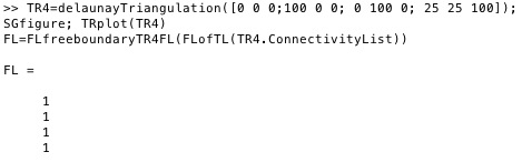 | % FLfreeboundaryTR4FL(TR4FL) - returns the freeBoundary facets of a % tetrahedron % (by Tim Lueth, VLFL-Lib, 2015-AUG-07 as class: TETRAHEDRONS) % % This procedure is tricky to use. Use only if you complete understand % what you want to do. % % This procedure processes a FL list that contains all surface facets of % a tetrahedron delaunay triangulation (ConnectivityList), created for % instance by % FL=[TL(:,[2 3 4]); TL(:,[2 4 1]); TL(:,[4 3 1]); TL(:,[2 1 3])]. % It analyzes which surface has no attached corresponding facet. Those % have to be the outside facets of the tetrahedron delaunay % triangulation, i.e. the freeBoundary. % % There exist in Matlab already a method freeBoundary for a tetrahedron % triangulation (nx4) which returns a facet list. There exist also a % method freeBoundary for a triangle triangulation (nx3) which returns an % edge list. % % (Status of: 2015-08-07) % % fb=FLfreeboundaryTR4FL(TR4FL) % === INPUT PARAMETERS === % TR4FL: Facet List of a tetrahedron triangulation (FLofTL) % === OUTPUT RESULTS ====== % fb: outside, free boundary facet index list % % EXAMPLE: % TR4=delaunayTriangulation([0 0 0;100 0 0; 0 100 0; 25 25 100]); % SGfigure; TRplot(TR4) % FL=FLfreeboundaryTR4FL(FLofTL(TR4.ConnectivityList)) % |
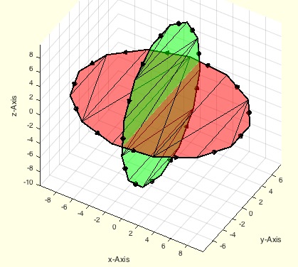
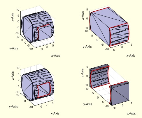
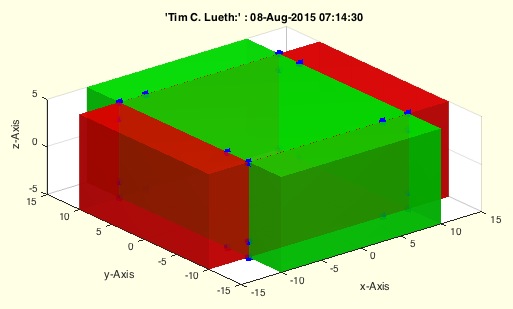
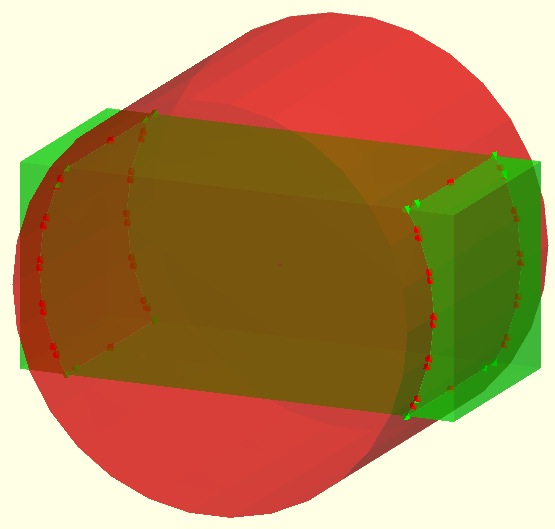
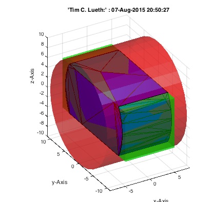
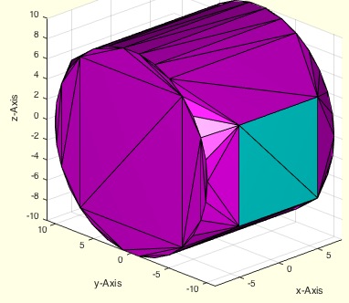
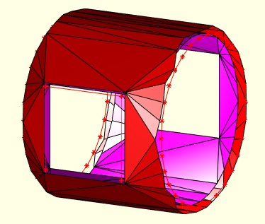
exp_2015_08_07- EXPERIMENT To XOR two solids by delaunay triangulation including crossing points |
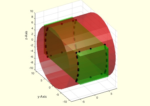 | %% PUBLISHABLE EXP_2015_08_07 EXPERIMENT TO XOR TWO SOLIDS BY DELAUNAY TRIANGULATION INCLUDING CROSSING POINTS % (by Tim Lueth, VLFL-Lib, 2015-AUG-07 as class: EXPERIMENTS) %% % exp_2015_08_07 - EXPERIMENT To XOR two solids by delaunay triangulation % including crossing points % (by Tim Lueth, VLFL-Lib, 2015-AUG-07 as class: EXPERIMENTS) % % exp_2015_08_07 % |
exp_2015_08_06- |
 | % exp_2015_08_06 - % (by Tim Lueth, VLFL-Lib, 2015-AUG-07 as class: EXPERIMENTS) % % exp_2015_08_06 % |
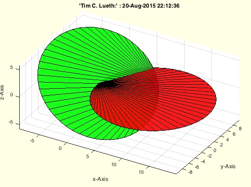
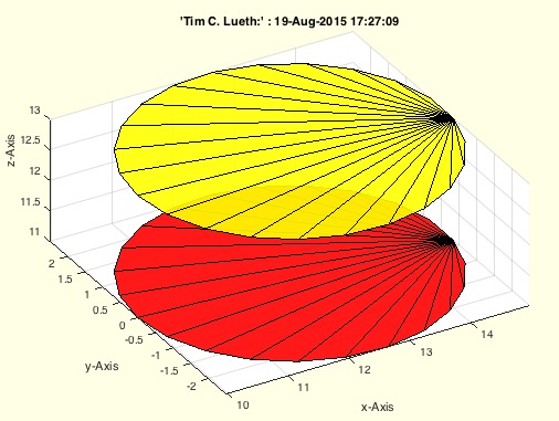
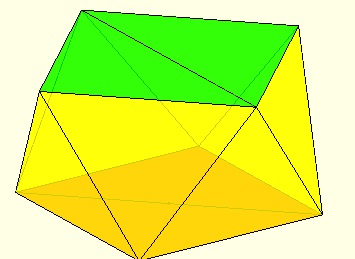
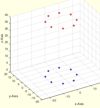
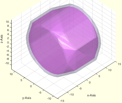
exp_2015_08_05- Experiment for understanding the creation of convex solids from border lines |
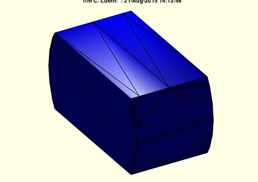 | %% PUBLISHABLE EXP_2015_08_05 EXPERIMENT FOR UNDERSTANDING THE CREATION OF CONVEX SOLIDS FROM BORDER LINES % (by Tim Lueth, VLFL-Lib, 2015-AUG-21 as class: EXPERIMENTS) %% % exp_2015_08_05 - Experiment for understanding the creation of convex % solids from border lines % % (by Tim Lueth, VLFL-Lib, 2015-AUG-21 as class: EXPERIMENTS) % % [NFL,VL]=exp_2015_08_05 % === OUTPUT RESULTS ====== % NFL: % VL: % |
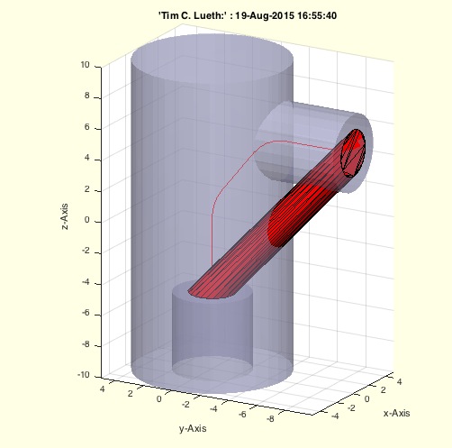
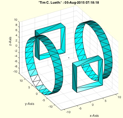
exp_2015_08_04- Experiment to generate tube connectors |
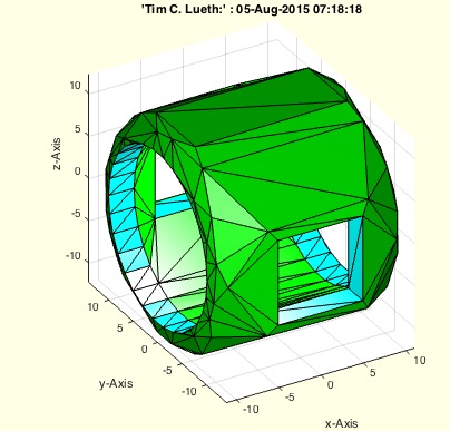 | %% PUBLISHABLE EXP_2015_08_04 EXPERIMENT TO GENERATE TUBE CONNECTORS % (by Tim Lueth, VLFL-Lib, 2015-AUG-05 as class: EXPERIMENTS) %% % exp_2015_08_04 - Experiment to generate tube connectors % (by Tim Lueth, VLFL-Lib, 2015-AUG-05 as class: EXPERIMENTS) % % exp_2015_08_04 % |
FLcontourwallFLn(FLA,FLB,n)- returns a simple wall contour between the boundaries of 2 identical surfaces |
 | % FLcontourwallFLn(FLA,FLB,n) - returns a simple wall contour between the % boundaries of 2 identical surfaces % (by Tim Lueth, VLFL-Lib, 2015-AUG-04 as class: SURFACES) % % FLA and FLB are planar open surfaces. The border line (freeBoundary ist % detected for of them). % % The use of the procedure is shown in exp_2015_08_04 to create tunnels % between the openings of an inner and outer shell. (Status of: % 2015-08-05) % % FLW=FLcontourwallFLn(FLA,FLB,n) % === INPUT PARAMETERS === % FLA: Facet list describing opening A % FLB: Facet list describing opening B % n: difference number between vertices % === OUTPUT RESULTS ====== % FLW: Facet List of the wall contour % |
SGofVLdelaunay(CVL)- returns a convex delaunay triangulation |
 | % SGofVLdelaunay(CVL) - returns a convex delaunay triangulation % (by Tim Lueth, VLFL-Lib, 2015-AUG-03 as class: SURFACES) % % Based on a cell list of individual vertex list, each is describing the % border/freeBoundary of a planar surface, a delaunay triangulation is % calculated. The tetrahedron triangulation is converted into a surface % triangualtion. A cell list describes the indices of the vertices and % the facet indices within the surface % % At a later stage in makes sense to reorder the facets by [FoL;FiL] % (Status of: 2015-08-04) % % [SG,ViL,FiL,FNL,FoL]=SGofVLdelaunay(CVL) % === INPUT PARAMETERS === % CVL: Cell list of Contour Vertex Lists {VL1,VL2,VL3} % === OUTPUT RESULTS ====== % SG: Solid Geometry (VL=[VL1;VL2,...]) % ViL: Vertex index list (n x 2) wit start and end index % FiL: Cells with Facet index Lists % FNL: Facet normal vector list % FoL: Facet index list for the surface without the enclosed ones % % EXAMPLE: A=SGbox([30,10,10]); % B=SGbox([10,30,10]); % [VL,FL,c,d]=SGofVLdelaunay({A.VL(1:end/2,:),A.VL(1+end/2:end,:) % ,B.VL(1:end/2,:),B.VL(1+end/2:end,:)}); % VLFLplots(VL,FL,'m'); % VLFLplots(VL,FL(d{4},:),'c'); % % |
exp_2015_08_03- |
 | % exp_2015_08_03 - % (by Tim Lueth, VLFL-Lib, 2015-AUG-03 as class: EXPERIMENTS) % % exp_2015_08_03 % |
SGgrow(SG,d,thr)- returns the same solid by with increased dimensions |
 | % SGgrow(SG,d,thr) - returns the same solid by with increased dimensions % (by Tim Lueth, VLFL-Lib, 2015-AUG-03 as class: SURFACES) % % grows a solid by adding the vertex normal vector to the vertex % coordinates multiplied by a factor d. ATTENTION, The MATLAB-original % vertex normal calculation is not always correct. Therefor in this fnctn % we used a different methods with some side effects too. % SGgrow fnctn is perfect to analyze the correctness of Surface Solids % % BTW: CATIA LIMITS THE SPATIAL RESOLUTION TO 0.01mm, ie. 1e-2 (Status % of: 2018-08-20) % % Introduced first in SolidGeometry 2.4 % % See also: SGmagnifyVL % % SGN=SGgrow(SG,d,[thr]) % === INPUT PARAMETERS === % SG: Solid Geometry % d: grow distance % thr: threshold for SGselect; default ist 1e-12 % === OUTPUT RESULTS ====== % SGN: resulting solid geoemtry % % See also: SGmagnifyVL % % % Copyright 2015-2019 Tim C. Lueth |
SGofBB(BB,d)- returns a solid for a bounding box |
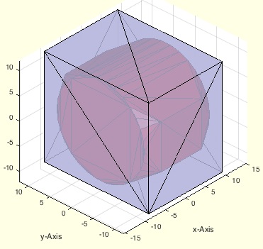 | % SGofBB(BB,d) - returns a solid for a bounding box % (by Tim Lueth, VLFL-Lib, 2015-AUG-03 as class: MODELING PROCEDURES) % % The bounding box can be increased in all direction by an distance % vector. d=[1 1 1] will lead to an enlargement of the bounding box by 2 % mm in the three x y z directions.. % For shape optimized cell type bounding boxes use BBofSG directly % (Status of: 2019-02-19) % % Introduced first in SolidGeometry 2.4 % % See also: BBiscollofVL, BBofVL, CPLofBB, VLFLofBB, outboundingbox, % BBofSG % % SG=SGofBB(BB,[d]) % === INPUT PARAMETERS === % BB: Result of BBofVL, i.e. [xmin xmax ymin ymax zmin zmax] % d: enlargement in [x y z]; default is d=[1 1 1] % === OUTPUT RESULTS ====== % SG: Solid box of size of the Bounding Box % % EXAMPLE: % SG=SGofCPLz(PLcircle(10,8),40); SGfigure(SG); view(-30,30); % SGofBB(BBofVL(SG.VL)) % % See also: BBiscollofVL, BBofVL, CPLofBB, VLFLofBB, outboundingbox, % BBofSG % % % Copyright 2015-2019 Tim C. Lueth |
TR3ofTR4(TR4,rem)- returns the surface triangulation of a tetrahedron |
 | % TR3ofTR4(TR4,rem) - returns the surface triangulation of a tetrahedron % (by Tim Lueth, VLFL-Lib, 2015-AUG-02 as class: TETRAHEDRONS) % % Single line procedure: % TR3=triangulation(freeBoundary(TR4),TR4.Points); % The procedure does not (!) remove unnecessary vertices unless rem=true % (default is false) (Status of: 2015-08-07) % % [TR3,VL,FL,SI]=TR3ofTR4(TR4,[rem]) % === INPUT PARAMETERS === % TR4: tetrahedron triangulation % rem: remove unused (internal) vertices; default is false % === OUTPUT RESULTS ====== % TR3: surface triangulation % VL: Vertex list % FL: Facet list % SI: FL=SI(FL) => maps to TR4.Points % % EXAMPLE: TR4=delaunayTriangulation([0 0 0;100 0 0; 0 100 0; 25 25 % 100]); % TR3ofTR4(TR4) % |
exp_2015_08_02- Experiment to generate tube connectors |
 | %% PUBLISHABLE EXP_2015_08_02 EXPERIMENT TO GENERATE TUBE CONNECTORS % (by Tim Lueth, VLFL-Lib, 2015-AUG-02 as class: EXPERIMENTS) %% % exp_2015_08_02 - Experiment to generate tube connectors % (by Tim Lueth, VLFL-Lib, 2015-AUG-02 as class: EXPERIMENTS) % % exp_2015_08_02 % |
depuseString(sstr,nocom,greps)- searches for string using the system command grep |
 | % depuseString(sstr,nocom,greps) - searches for string using the system command grep % (by Tim Lueth, VLFL-Lib, 2015-AUG-01 as class: FILE HANDLING) % % This fnctn is much faster than depuseTL or depuse, but returns all rows % with the occurrence of the fnctn. It is helpful to decide with the eye % whether older fnctns have to be corrected when changing parameters. % (Status of: 2022-02-10) % % Introduced first in SolidGeometry 2.4 % % See also: unixgrep, depuseTL, depuseToolbox, publishTL, pcodeTL, % depfunTL, pcodedirTL, SGfindswitchcaseconditions, searchdirTL, whichTL % % [l,f]=depuseString(sstr,[nocom,greps]) % === INPUT PARAMETERS === % sstr: search string % nocom: if true; comment lines s are ignored; default is false % greps: default is *.m % === OUTPUT RESULTS ====== % l: list of lines in the files of the current dirctory % f: list of mfiles that contains the string % % EXAMPLE: Search for tangentcirc % depuseString('tangentcirc') % Show all lines that use the term % depuseString('tangentcirc',true) % show all code lines that use the termi % [l,f]=depuseString('tangentcirc',true); % show only the fnct to modify % % See also: unixgrep, depuseTL, depuseToolbox, publishTL, pcodeTL, % depfunTL, pcodedirTL, SGfindswitchcaseconditions, searchdirTL, whichTL % % % Copyright 2015-2022 Tim C. Lueth |
edgeNormal(VL,VNL,EL)- returns the edge normals of surface boundaries |
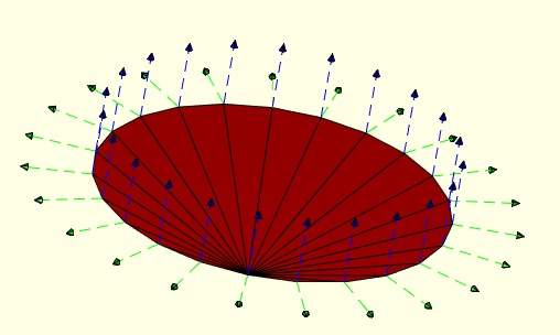 | % edgeNormal(VL,VNL,EL) - returns the edge normals of surface boundaries % (by Tim Lueth, VLFL-Lib, 2015-AUG-01 as class: SURFACES) % % This fnctn is in fact "edge-starting-vertex-orthogonal-vector" and % returns a list of the selected vertices vi % In case of a planar or freeform surface that is not closed(!) there % exist a border line (freeBoundary). This fnctn calculates the normal % vectors of the edge list vertices, i.e. the cross product of the line % from the previous to the next vertex of a vertex of an edge with the % normal vector of this vertic on the surface. (Status of: 2017-07-15) % % Introduced first in SolidGeometry 2.4 % % See also: edgeNormal, CPLedgeNormal, VLedgeNormal, PLnorm, PLELnorm, % PLFLfaceNormalVertex, orthogonal, vector, of, the, vertex, in, the, % first, column, of, the, edge, list, VLnorm, VLFLnormf, VLFLfaceNormal % % [VOL,c]=edgeNormal(VL,VNL,[EL]) % === INPUT PARAMETERS === % VL: Vertex list (nx3) % VNL: Vertex normal list (nx3) (i.e. vertexNormal) % EL: Edge list (i.e. freeBoundary) % === OUTPUT RESULTS ====== % VOL: Vertex orthogonal vector of the starting vertex in the edge list % c: starting vertex index list = EL(:,1) % % EXAMPLE: [SG,FLW]=SGsphere(10,'',pi/3,-pi/3); SG.FL=FLW; % SG=SGtransR(SG,rot(pi/6,0,0)); SGfigure(SG); view(-30,30); VL=SG.VL; % FL=SG.FL; % [VL,FL]=PLFLofCPLdelaunay(PLcircle(1)); VL=VLaddz(VL); % TR3=triangulation(FL,VL); % NL=vertexNormal(TR3); % EL=freeBoundary(TR3); % edgeNormal(VL,NL,EL) % % % See also: edgeNormal, CPLedgeNormal, VLedgeNormal, PLnorm, PLELnorm, % PLFLfaceNormalVertex, orthogonal, vector, of, the, vertex, in, the, % first, column, of, the, edge, list, VLnorm, VLFLnormf, VLFLfaceNormal % |
separateNaN(VL,i)- separates List by NaN rows entries |
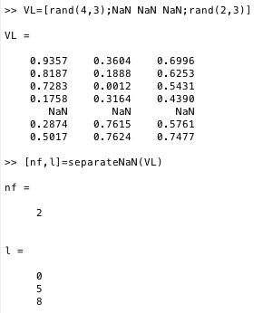 | % separateNaN(VL,i) - separates List by NaN rows entries % (by Tim Lueth, VLFL-Lib, 2015-JUL-31 as class: AUXILIARY PROCEDURES) % % n=separateNaN(VL); for i=1:n; myfunc(separateNaN(VL,i); end; (Status % of: 2019-07-08) % % Introduced first in SolidGeometry 2.4 % % See also: lengthNaN, replaceNaN, cellofNaN, selectNaN, uniqueNaN, % unsortNaN % % [x,a]=separateNaN(VL,i) % === INPUT PARAMETERS === % VL: List of nan separated sublists % i: optional number of sublist % === OUTPUT RESULTS ====== % x: List i or number of lists if nargin==1 % a: list of [0 nans size(VL,2)+1] % % EXAMPLE: how to use % nf=separateNaN(FL); if nf>1; for i=1:nf; PL=separateNaN(FL,i); end; % Example: % VL=[rand(4,3);NaN NaN NaN;rand(2,3)] % [nf,l]=separateNaN(VL) % separateNaN(VL,2) % % See also: lengthNaN, replaceNaN, cellofNaN, selectNaN, uniqueNaN, % unsortNaN % % % Copyright 2015-2020 Tim C. Lueth |
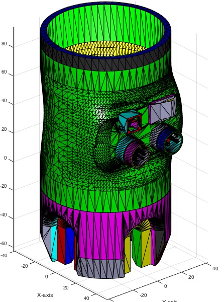
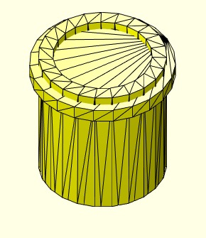
SGofSurface(OVL,OFL,t,d,s,cn)- returns a fitting solid relativ to a surface |
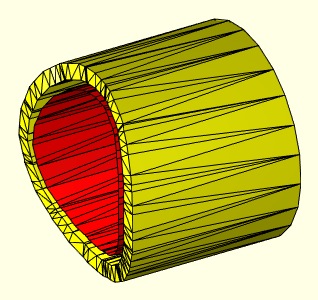 | % SGofSurface(OVL,OFL,t,d,s,cn) - returns a fitting solid relativ to a surface % (by Tim Lueth, VLFL-Lib, 2015-JUL-30 as class: SURFACES) % % Fast and stable fnctn even for large data sets. % This fnctn supports also facets list of type cell: {FL1,FL2,FL3}. % It also supports facets list separated by NaN: [FL1;NaN NaN NaN;FL2] % For planar ring, touch the crossing surface (Status of: 2018-08-24) % % Introduced first in SolidGeometry 2.4 % % See also: VLtransN, VLFLvertexNormal % % [SG,VL1,VL2,FLW]=SGofSurface(OVL,OFL,[t,d,s,cn]) % === INPUT PARAMETERS === % OVL: Vertex list of a surface (nx3) % OFL: Facet list of a surface (nx3) % t: thickness of the solid; default is 0.5 % d: distance from the surface; default is 0.3 % s: streching of the border line; default is 0 % cn: false=matlab vertex calc; true=corrected vertex normal; default is % false; true is 10 times slower -> VLFLvertexNormal % === OUTPUT RESULTS ====== % SG: resulting solid that can be attached to the surface % VL1: VL oved along d % VL2: VL moved d*ez % FLW: Facet of list wall [VL1;VL2] % % EXAMPLE: Surface clouds to solid geometries % loadweb 'AAruffo_surf.mat' % SGofSurface(SG1.VL,SG1.FL,-5,0); A=ans % SGpuzzlecut3D(A); X=ans; % SGboxpacking(X,[],[500 500 500]) % % See also: VLtransN, VLFLvertexNormal % % % Copyright 2015-2018 Tim C. Lueth |
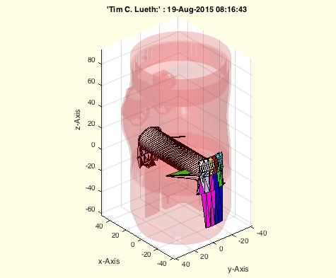
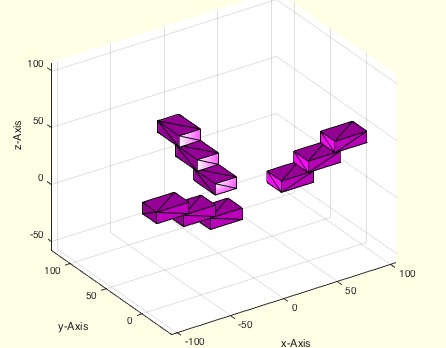
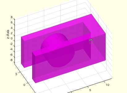
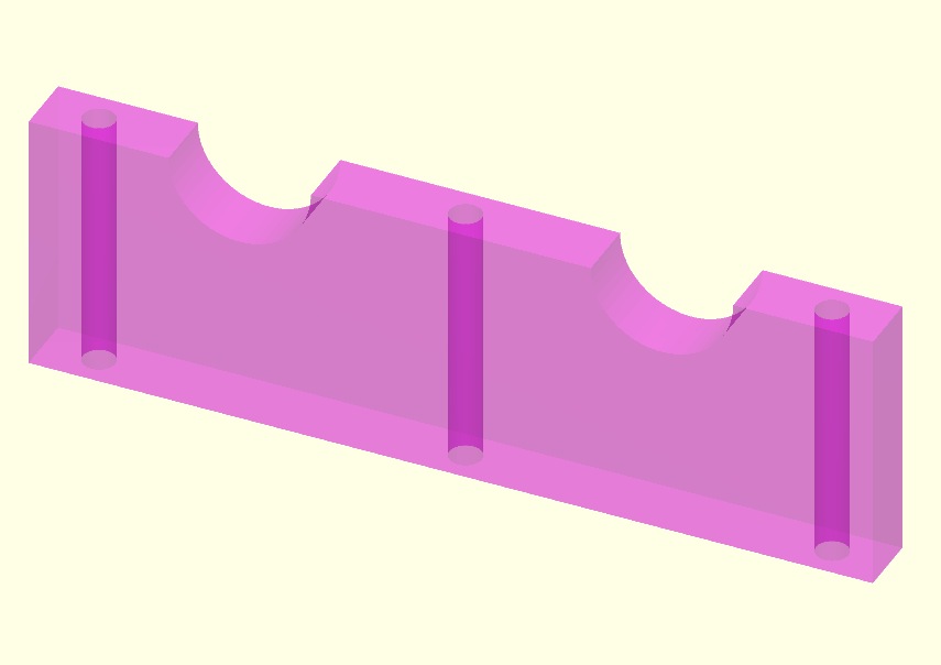
exp_2015_07_28- EXPERIMENT to test SGofSurface |
 | % exp_2015_07_28 - EXPERIMENT to test SGofSurface % (by Tim Lueth, VLFL-Lib, 2015-JUL-28 as class: EXPERIMENTS) % % This fnctn shows how from surfaces attaching solids can be generated % (Status of: 2018-08-20) % % Introduced first in SolidGeometry 2.4 % % See also: SGofSurface, SGTui, ELofjointFL % % A=exp_2015_07_28 % === OUTPUT RESULTS ====== % A: resulting solid body % % See also: SGofSurface, SGTui, ELofjointFL % % % Copyright 2015-2022 Tim C. Lueth |
SGcopyrotZ(SG,rotangz,tdist,n)- copies a solid around the z-axis |
 | % SGcopyrotZ(SG,rotangz,tdist,n) - copies a solid around the z-axis % (by Tim Lueth, VLFL-Lib, 2015-JUL-27 as class: AUXILIARY PROCEDURES) % % Introduced first in SolidGeometry 2.4 % % See also: SGboxing, SGcopypatternXYZ, SGpatternRotz, SGarrangeSG, % SGarrangeSGC, SGCaddSGn, SGCaddSG, SGstackn, SGcopyVL, SGsurfaces % % SGN=SGcopyrotZ(SG,rotangz,[tdist,n]) % === INPUT PARAMETERS === % SG: Solid geoemtry % rotangz: list of rotation angles % tdist: translation vector before each copy % n: number of repeats % === OUTPUT RESULTS ====== % SGN: resulting solid % % EXAMPLE: % SGcopyrotZ(SGbox,pi/3,[100 0 0]) % SGcopyrotZ(SGtrans1(SGbox([30,20,10])),[0 pi/2 pi],[25 0 10],3) % % % See also: SGboxing, SGcopypatternXYZ, SGpatternRotz, SGarrangeSG, % SGarrangeSGC, SGCaddSGn, SGCaddSG, SGstackn, SGcopyVL, SGsurfaces % % % Copyright 2015-2021 Tim C. Lueth |
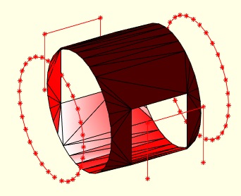
CPLcopypattern(CPL,number,delta)- creates patterns by copying CPLs |
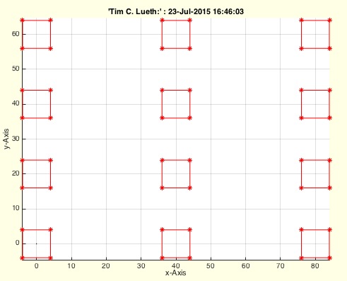 | % CPLcopypattern(CPL,number,delta) - creates patterns by copying CPLs % (by Tim Lueth, VLFL-Lib, 2015-JUL-23 as class: CLOSED POLYGON LISTS) % % Introduced first in SolidGeometry 2.4 % % See also: CPLcopypattern, CPLcopypatternPL, SGpatternRotz, % CPLcopyradial, CPLcopypatternTL % % CPLN=CPLcopypattern(CPL,number,delta) % === INPUT PARAMETERS === % CPL: Original Polygon % number: copy vector [nx ny] % delta: distance vector [dx dy] % === OUTPUT RESULTS ====== % CPLN: New closed polygon line % % EXAMPLE: A=CPLcopypattern; % SGofCPLz(A,40);view (-30,30); % % See also: CPLcopypattern, CPLcopypatternPL, SGpatternRotz, % CPLcopyradial, CPLcopypatternTL % % % Copyright 2015-2021 Tim C. Lueth |
SGparts(Nr,TLPAR,sl,ol)- Often used solid geometries additive designed |
 | % SGparts(Nr,TLPAR,sl,ol) - Often used solid geometries additive designed % (by Tim Lueth, VLFL-Lib, 2015-JUL-16 as class: MODELING PROCEDURES) % % ======================================================================= % OBSOLETE (2022-04-14) - USE 'SGsample' INSTEAD % ======================================================================= % % RENAMED TO _SGparts (THIS FNCTN IS OUTDATED) % Default parameters are: % Overlap: ol=0.1 % Slot distances: sl=0.3 % For the rest it is necessary to read the manual % 001 - sz=[x y z] (Box) % 002 - r=radius, h=height (Cylinder) % (Status of: 2018-08-20) % % Introduced first in SolidGeometry 2.4 % % SG=SGparts(Nr,[TLPAR,sl,ol]) % === INPUT PARAMETERS === % Nr: Part number % TLPAR: Parameterstring for the definition of dimensions % sl: slot size for separated objects; default is 0.5 % ol: overlap for additive objects; default is 0.1 % === OUTPUT RESULTS ====== % SG: Final solid geometry % % % Copyright 2015-2022 Tim C. Lueth |
exp_2015_07_16 (varstr)- EXAMPLE for a very elegant method to transfer variable definitions |
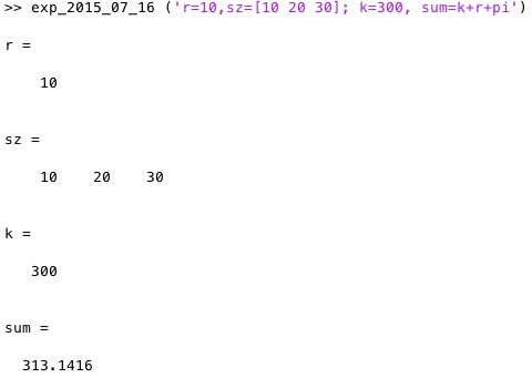 | % exp_2015_07_16 (varstr) - EXAMPLE for a very elegant method to transfer % variable definitions % (by Tim Lueth, VLFL-Lib, 2015-JUL-16 as class: AUXILIARY PROCEDURES) % % This is not a fast but very elegant method to declare variables by a % parameterstrinf directly in Matlab Syntax (Status of: 2015-07-16) % % exp_2015_07_16(varstr) % === INPUT PARAMETERS === % varstr: parameter variable string, for example (varargin{1}) % % EXAMPLE: exp_2015_07_16 ('r=10,sz=[10 20 30]; k=300, sum=k+r+pi') % |
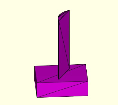
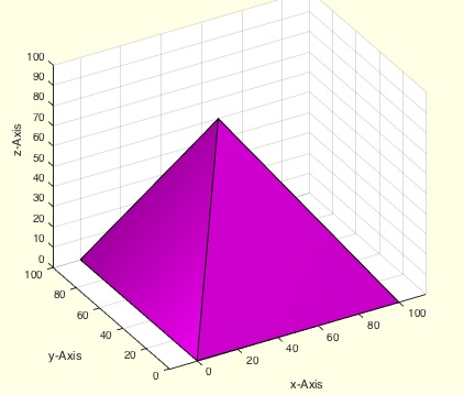
CAD_1_1- PUBLISHABLE EXAMPLE of Excercise CAD 1.1 |
 | % CAD_1_1 - PUBLISHABLE EXAMPLE of Excercise CAD 1.1 % (by Tim Lueth, VLFL-Lib, 2015-JUL-14 as class: MODELING PROCEDURES) % % This procedure is an example how to solve the excercise 1.1 of the % "Rechnerintegrierte Produktentwicklung - CAD und CAD/CAM" (2015) % of Professor Dr.-Ing. Udo Lindemann (Status of: 2015-07-14) % % CAD_1_1 % % EXAMPLE: web(publish ('CAD_1_1')); % |
CAD_1_2- PUBLISHABLE EXAMPLE of Excercise CAD 1.2 |
 | % CAD_1_2 - PUBLISHABLE EXAMPLE of Excercise CAD 1.2 % (by Tim Lueth & Laurans de Smedt, VLFL-Lib, 2015-JUN-29 as class: % MODELING PROCEDURES) % % This procedure is an example how to solve the excercise 1.2 of the % "Rechnerintegrierte Produktentwicklung - CAD und CAD/CAM" (2015) % of Professor Dr.-Ing. Udo Lindemann (Status of: 2015-06-29) % % CAD_1_2 % |
SGfigure(VL,FL)- Application for opening and viewing STL Files |
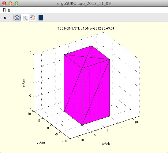 | % SGfigure(VL,FL) - Application for opening and viewing STL Files % (by Tim Lueth, VLFL-Lib, 2015-JUN-22 as class: VISUALIZATION) % % Since SG-Lib 4.9 this fnctn is not chaning the light condition anymore % to speed up rotation % The fnctn can be compiled as application or used as user interface % fnctn. Called without input parameters, a file reading dialog will be % opened. There are examples for reading, writing of STL files and % changing light condition or grid information. % It should show the potential of Matlab to the company Arburg, Lossburg % (Status of: 2020-01-13) % % Introduced first in SolidGeometry 2.4 % % See also: VLFLfigure, SGtitle, select3d, pixelofaxis, VLFLplotlight, % SGfigurevideo, SGfigureannotation, hindeingca, findingca % % h=SGfigure([VL,FL]) % === INPUT PARAMETERS === % VL: Vertex list of solid geometry; or SG or az of view % FL: Facet list of solid geometry or el of viee % === OUTPUT RESULTS ====== % h: handle to figure % % EXAMPLE: GUI with a small cube (0.1 0.1 0.1) in the center: % SGfigure; % SGfigure(SGbox); % SGfigure(0,0); % % See also: VLFLfigure, SGtitle, select3d, pixelofaxis, VLFLplotlight, % SGfigurevideo, SGfigureannotation, hindeingca, findingca % % % Copyright 2015-2020 Tim C. Lueth |
PLtoolTip(d1,d2,w)- creates a PL fo SGtoolMilling |
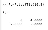 | % PLtoolTip(d1,d2,w) - creates a PL fo SGtoolMilling % (by Tim Lueth, VLFL-Lib, 2015-JUN-21 as class: MECHANICAL PROCEDURES) % % PL=PLtoolTip(d1,d2,[w]) % === INPUT PARAMETERS === % d1: outer diameter % d2: tip diameter % w: optional angle; default is 90 % === OUTPUT RESULTS ====== % PL: Point list % |
SGcut2(SG,z)- Cuts a solid geometry by inserting vertices and facets |
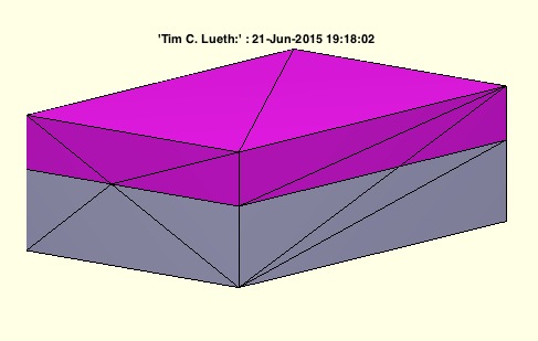 | % SGcut2(SG,z) - Cuts a solid geometry by inserting vertices and facets % (by Tim Lueth, VLFL-Lib, 2015-JUN-21 as class: SURFACES) % % returns one modified solid that has additional vertices and facets % along the cutting plane. In contrast to SGcut is delivers always % exactly one solid and accepts only one z coordinate. If the fnctns is % called twice with the same z-coordinates, no additional points are % created. For this purpose it was necessary to modify the fnctn % SCslicer. (Status of: 2018-11-06) % % Introduced first in SolidGeometry 2.4 % % See also: SGcut, SGcutBB, SGcutT, BBofSGcutT % % [SGA]=SGcut2(SG,z) % === INPUT PARAMETERS === % SG: Solid Geometry (VL,FL) % z: z value for slicing % === OUTPUT RESULTS ====== % [SGA]: Solid below cutting plane (and above z2) % % EXAMPLE: SGcut2 (SGbox([30,20,10]),1); % % See also: SGcut, SGcutBB, SGcutT, BBofSGcutT % % % Copyright 2015-2018 Tim C. Lueth |
exp_2015_06_19- EXPERIMENT that is the origin of SGmilling |
 | % exp_2015_06_19 - EXPERIMENT that is the origin of SGmilling % (by Tim Lueth, VLFL-Lib, 2015-JUN-19 as class: EXPERIMENTS) % % A=exp_2015_06_19 % === OUTPUT RESULTS ====== % A: % % EXAMPLE: % A=exp_2015_06_19; % VLFLfigure(A) % |
VILofrangez(VL,FL,z,thr)- returns indices of VL and FL in a cut plane |
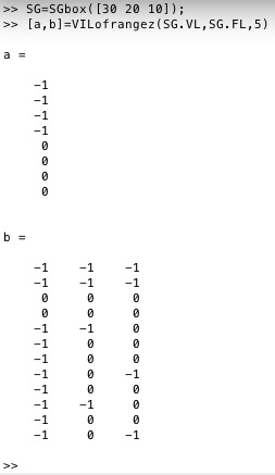 | % VILofrangez(VL,FL,z,thr) - returns indices of VL and FL in a cut plane % (by Tim Lueth, VLFL-Lib, 2015-JUN-19 as class: SLICES) % % The vertex index list shows relation of the vertex z coordinate related % to the cutting plane: +1 = above plane, -1 under plane, 0=crosses % plane. The crossing facet list explains the crossing situation % 0 0 0 All points in plane (1) % -1 -1 -1 All points under plane (1) % +1 +1 +1 All points above plane (1) % 0 0 +1 One point above (3) % 0 0 -1 One point under (3) % 0 +1 +1 One point on plane, two above (3) % 0 -1 -1 One point on plane, two under (3) % 0 +1 -1 One point on plane, one above, one under (3) % 0 -1 +1 One point on plane, one above, one under (3) % -1 +1 +1 One point under, one point above (3) % +1 -1 -1 One point under, one point above (3) % overall 27 combinatons (Status of: 2015-06-19) % % [VIL,CFL]=VILofrangez(VL,FL,z,[thr]) % === INPUT PARAMETERS === % VL: Vertex list % FL: Facet list % z: cut coordinate % thr: optional grid; default is 1e-5 % === OUTPUT RESULTS ====== % VIL: +1 = above plane, -1 under plane, 0=crosses plane % CFL: Crossing Facet List % % EXAMPLE: SG=SGbox([30 20 10]); % [a,b]=VILofrangez(SG.VL,SG.FL,5) % |
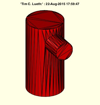
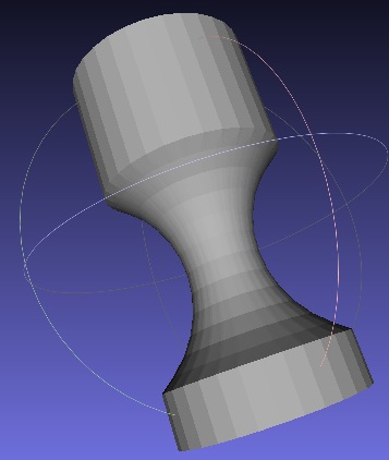
SGtoolMilling(A,PL)- returns a solid geometry resulting by a milling process |
 | % SGtoolMilling(A,PL) - returns a solid geometry resulting by a milling % process % (by Tim Lueth, VLFL-Lib, 2015-JUN-16 as class: SURFACES) % % SG=SGtoolMilling(A,PL) % === INPUT PARAMETERS === % A: Solid Geometry % PL: rz-List milling contour (nx2) % === OUTPUT RESULTS ====== % SG: resulting solid % % EXAMPLE: % A=SGthread(10,30) % SGtoolMilling(A,PLtoolTip(10,8)) % |
SGtoolTip (d1,d2,w)- returns a SG for a "tool" for SGbool |
 | % SGtoolTip (d1,d2,w) - returns a SG for a "tool" for SGbool % (by Tim Lueth, VLFL-Lib, 2015-JUN-16 as class: EXPERIMENTS) % % Many DIN and ISO standards for machine elements expect a point tip % shape at the end of a screw. This SGtool can be used as negtive form % for shaping a tip of a bolt or screw etc. (Status of: 2015-06-16) % % SGtoolTip(d1,d2,[w]) % === INPUT PARAMETERS === % d1: outer diameter % d2: tip diameter % w: optional angle; default is 90 degree % |
exp_2015_06_16 (d1,d2,w)- EXPERIMENT to create a SGBool-Tool for point tips of screws |
 | % exp_2015_06_16 (d1,d2,w) - EXPERIMENT to create a SGBool-Tool for point % tips of screws % (by Tim Lueth, VLFL-Lib, 2015-JUN-16 as class: EXPERIMENTS) % % exp_2015_06_16(d1,d2,[w]) % === INPUT PARAMETERS === % d1: outer diameter % d2: tip diameter % w: optional angle; default is 90 degree % |
SGiso4026(M,L,imb)- SG of Hexagon socket set screw with flat point |
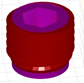 | % SGiso4026(M,L,imb) - SG of Hexagon socket set screw with flat point % (by Tim Lueth, VLFL-Lib, 2015-JUN-15 as class: MECHANICAL PROCEDURES) % % returns a solid geometry of a "Hexagon socket set screw with flat % point" related to DIN913 or ISO4026 (Status of: 2017-01-29) % % See also: DINhelp, DIN913, DIN912, DIN336, SGiso4762 % % SG=SGiso4026(M,L,[imb]) % === INPUT PARAMETERS === % M: Diameter (millimeter) % L: Length (millimeter) % imb: true=imbus; false=simple screw % === OUTPUT RESULTS ====== % SG: Solid geoemetry of Hexagon socket set screw with flat point % |
DIN913(M)- returns the DIN913/ISO4026 table for a metric threads |
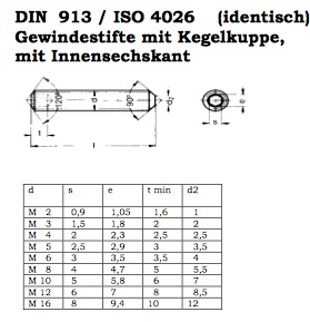 | % DIN913(M) - returns the DIN913/ISO4026 table for a metric threads % (by Tim Lueth, VLFL-Lib, 2015-JUN-15 as class: MECHANICAL PROCEDURES) % % The table DIN913/ISO4026 has the following columns. All values are % given in millimeter % 1) Metric outer diameter in mm % 2) Imbus width % 3) Tip diameter % 4) unknown % 5) Depth of imbus (Status of: 2020-08-04) % % Introduced first in SolidGeometry 2.4 % % See also: DIN13, DIN336, DIN464, DIN912, DIN985, DINfindinTab, DINhelp, % DINthreadtorque % % [M,TL]=DIN913(M) % === INPUT PARAMETERS === % M: metric treat diameter % === OUTPUT RESULTS ====== % M: M that was used for the table entry % TL: Table entry for M % % See also: DIN13, DIN336, DIN464, DIN912, DIN985, DINfindinTab, DINhelp, % DINthreadtorque % % % Copyright 2015-2020 Tim C. Lueth |
DINhelp- open different urls for DIN and ISO Standard Machine Elements |
 | % DINhelp - open different urls for DIN and ISO Standard Machine Elements % (by Tim Lueth, VLFL-Lib, 2015-JUN-15 as class: MECHANICAL PROCEDURES) % % The German company Wegertseder offeres summaries of DIN/ISO standards % for fixation elements (Status of: 2020-08-04) % % Introduced first in SolidGeometry 2.4 % % See also: DIN13, DIN336, DIN464, DIN912, DIN913, DIN985, DINfindinTab, % DINthreadtorque % % DINhelp % % EXAMPLE: just enter DINhelp for opening the pae % % See also: DIN13, DIN336, DIN464, DIN912, DIN913, DIN985, DINfindinTab, % DINthreadtorque % % % Copyright 2015-2020 Tim C. Lueth |
interPL(PL,x)- returns a value as linear interpolation using a PL |
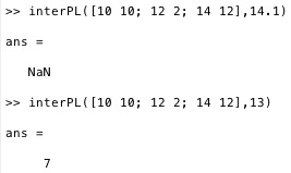 | % interPL(PL,x) - returns a value as linear interpolation using a PL % (by Tim Lueth, VLFL-Lib, 2015-JUN-15 as class: AUXILIARY PROCEDURES) % % Returns a linear interpolation value y using a Point list (nx2) % consisting of x and y values. If the input parameter is outside of the % defined interval the procedure return NaN. At a later stage it makes % sense to introduce a third parameter for different interpolation % procedures (splines etc.). % ATTENTION: The point list has to be sorted using PL=sortrows(PL,1) % before calling the procedure. (Status of: 2015-06-19) % % y=interPL(PL,x) % === INPUT PARAMETERS === % PL: Point list (nx2) using x and y values % x: input value within the interval of xmin and xmax of PL % === OUTPUT RESULTS ====== % y: interpolated value for y or NaN outside of xmin and xmax of PL % % EXAMPLE: find interpolation values for a simple point list for x=13 % interPL([10 10; 12 2; 14 12],13) % |