CPL2line(CPLo,dx)- converts a line type contour into a line by considering only the half of the contour |
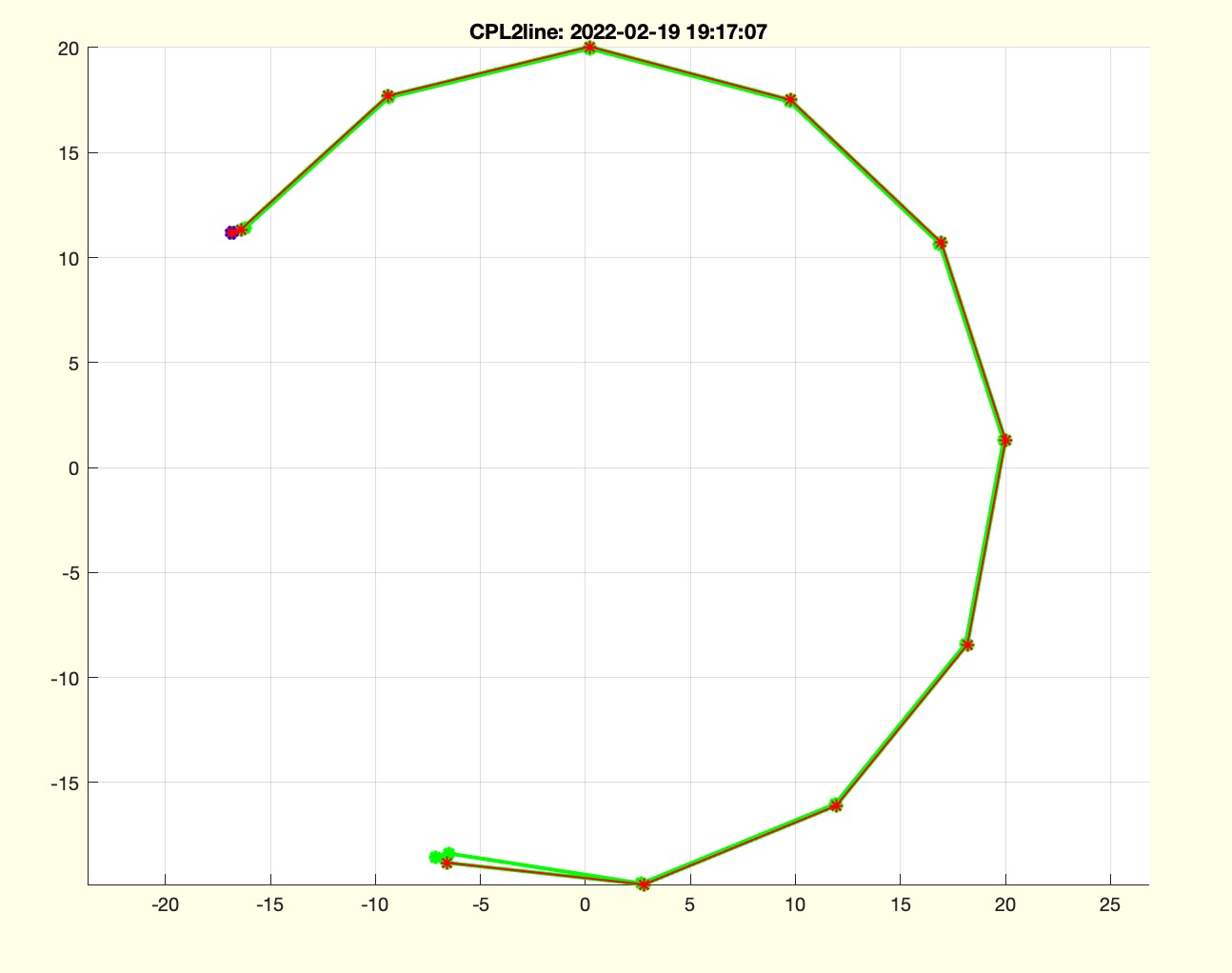 | % CPL2line(CPLo,dx) - converts a line type contour into a line by considering only the half of the contour % (by Tim Lueth, VLFL-Lib, 2022-FEB-18 as class: CLOSED POLYGON LISTS) % % Introduced first in SolidGeometry 5.1 % % See also: CPLregionshrink % % CPLN=CPL2line(CPLo,[dx]) % === INPUT PARAMETERS === % CPLo: Original CPL % dx: expected distance between both boundaries; default is 0.1 % === OUTPUT RESULTS ====== % CPLN: PL of contour % % EXAMPLE: % CPL2line(CPLregionshrink(PLtransR(CPLsample(35),pi/10))) % CPL2line(CPLregionshrink(PLtransR(CPLsample(18),pi/10))) % % See also: CPLregionshrink % % % Copyright 2022 Tim C. Lueth |
CPLlength(CPL)- returns the boundary length of a CPL |
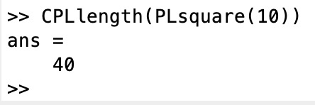 | % CPLlength(CPL) - returns the boundary length of a CPL % (by Tim Lueth, VLFL-Lib, 2022-FEB-18 as class: CLOSED POLYGON LISTS) % % same as ps=polyshape(CPL(:,1),CPL(:,2)); len=ps.perimeter; % (Status of: 2022-02-18) % % Introduced first in SolidGeometry 5.1 % % See also: CPLarea % % len=CPLlength(CPL) % === INPUT PARAMETERS === % CPL: CPL % === OUTPUT RESULTS ====== % len: len of contur line % % EXAMPLE: % CPLlength(PLsquare(10)) % % See also: CPLarea % % % Copyright 2022 Tim C. Lueth |
CPLregionshrink(CPL,dlim,rsep)- returns the smallest shrinked contour with same dimensions, regions and holes |
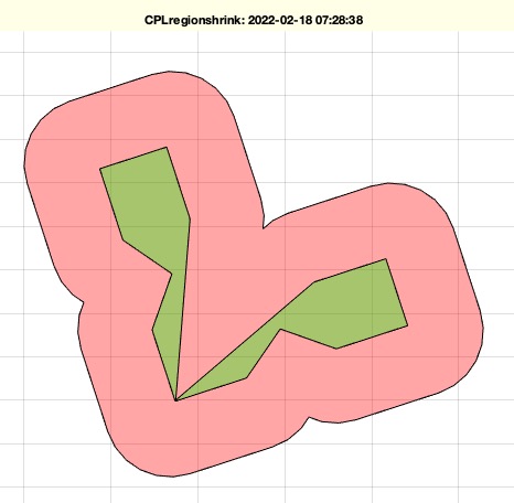 | % CPLregionshrink(CPL,dlim,rsep) - returns the smallest shrinked contour with same dimensions, regions and holes % (by Tim Lueth, VLFL-Lib, 2022-FEB-18 as class: CLOSED POLYGON LISTS) % % will always return areas, even point shaped or line shaped % powerful fnctn ! (Status of: 2022-02-18) % % Introduced first in SolidGeometry 5.1 % % See also: CPLbuffer, CPL2line % % [CPLo,dx]=CPLregionshrink(CPL,[dlim,rsep]) % === INPUT PARAMETERS === % CPL: Contour to shrink % dlim: accuracy; default is 0.01 % rsep: if true; the limit is individual to each fnctn; default is true; % === OUTPUT RESULTS ====== % CPLo: shinked contour with same number of regions and holes % dx: limit of last shinkage % % EXAMPLE: % CPLregionshrink(PLtransR(CPLsample(40),pi/10)); % just before breaking into different regions % CPLregionshrink(PLtransR(CPLsample(18),pi/10)); % just before region disappears as line % CPLregionshrink(PLtransR(CPLsample(22),pi/10),0.01) % just before region disappears as point % % % See also: CPLbuffer, CPL2line % % % Copyright 2022 Tim C. Lueth |
fourBarCLLL2SGdesign(CLLL,R12,RACK,"layer","debug","assembly","mirrR","massE","L")- Converts a contour layered link list into a real solid geometry construction to 3D print |
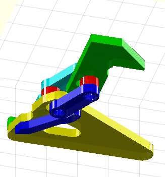 | % fourBarCLLL2SGdesign(CLLL,R12,RACK,"layer","debug","assembly","mirrR") - Converts a contour layered link list into a real solid geometry construction to 3D print % (by Tim Lueth, VLFL-Lib, 2022-FEB-15 as class: KINEMATICS AND FRAMES) % % The Contour Layer Link List has the following order % [CPLE;CPLC;CPLS;CPLG;CPLW;CPLA0;CPLB0;CPLA1;CPLB1] % Each cell list row of this 9x5 cell list has the format % {Name, CPL, TL, col, [Lmin lmax]} % This fnctn does not check collisions, but simply extrudes the bodies % and constructs the assembly method % The process: % Posesample => Posedefiniton % fourBarposesyntheses => compute fourbars % fourBarposeplotsolution => plot or animate solutions % fourBarposelayering => layer and compute shape % fourBarCLLL2SGdesign => Design for assembly and 3D print (Status of: % 2022-02-22) % % Introduced first in SolidGeometry 5.1 % % See also: Posesample, fourBarposesyntheses, fourBarposeplotsolution, % fourBarposelayering % % [SG,SLLL]=fourBarCLLL2SGdesign(CLLL,[R12,RACK,"layer","debug","assembly % ","mirrR"]) % === INPUT PARAMETERS === % CLLL: contour layered link list % R12: [Ro Ri H]; default is 5 2.5 6] % RACK: Additional Rack Points for Fixation % "layer": not recommended but possible to change the layers [CPLR CPLE % CPLC CPLS CPLW] % "debug": if used, the design is shown step by step % "assembly": 'DIN912985' or 'DIN912BUSH' or 'DIN7991' as assembly method % "mirrR": % === OUTPUT RESULTS ====== % SG: Cell list of Solid Gemetries % SLLL: Same as CLLL but with SGs instead of CPLs % % SLLL={SGE;SGC;SGS;SGG;SGW;SGA0;SGB0;SGA1;SGB1} % % EXAMPLE: % % fourBarCLLL2SGdesign(LLLM), shg % [a,b]=fourBarCLLL2SGdesign(LLLM,'layer',[0 1 1 2]), shg % EXTREME RISKY TO MODIFY THE LAYERING % for i=1:size(SLLL,1); SGplotalpha(SGtransT(SLLL{i,2},T3ofT2(SLLL{i,3}(:,:,1)))); end; rotate3d on; % % % See also: Posesample, fourBarposesyntheses, fourBarposeplotsolution, % fourBarposelayering % % % Copyright 2022 Tim C. Lueth |
CPLremconvexcorner(CPL)- remove single convex corners from the contour |
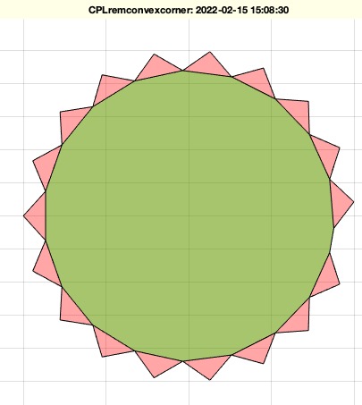 | % CPLremconvexcorner(CPL) - remove single convex corners from the contour % (by Tim Lueth, VLFL-Lib, 2022-FEB-15 as class: CLOSED POLYGON LISTS) % % In case of swept volumes often there aris corners from the cutting out % squres on a circluar path (Status of: 2022-02-15) % % Introduced first in SolidGeometry 5.1 % % See also: CPLsweep, CPLsweepTL, CPLunionTL, CPLsubtractTL % % % CPLN=CPLremconvexcorner(CPL) % === INPUT PARAMETERS === % CPL: Contour % === OUTPUT RESULTS ====== % CPLN: contour with removed corners % % EXAMPLE: % CPLremconvexcorner(PLstar(10)) % % See also: CPLsweep, CPLsweepTL, CPLunionTL, CPLsubtractTL % % % % Copyright 2022 Tim C. Lueth |
testparsing(fname,cmdstr)- performs an interactive test parsing of a grammar fnct |
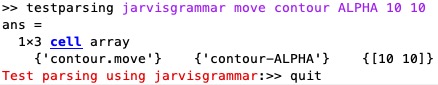 | % testparsing(fname,cmdstr) - performs an interactive test parsing of a grammar fnct % (by Tim Lueth, VLFL-Lib, 2022-FEB-15 as class: USER INTERFACE) % % to test the parsing of grammarfnctn, it is necessary to repeat a lot of % input string chains. Therefor it is helpful to have an user mode in % which inputs are processed but without executing of the command. This % requires a loop including the user interface command input. To avoid % the implementation of thos input loops as part if the grammar fnctn, % this fnctn just takes an input, calls the grammar fnctn and repeats it % until a quit command is used % % This fnctn is also an tutorial how to implement natural language % interpreter interfaces (Status of: 2022-02-15) % % Introduced first in SolidGeometry 5.1 % % See also: jarvisgrammar % % testparsing(fname,[cmdstr]) % === INPUT PARAMETERS === % fname: name of the grammar fnctn such as jarvisgrammar % cmdstr: optional command string for testing % % EXAMPLE: % testparsing jarvisgrammar move contour ALPHA 10 10 % processes already a string chain % testparsing jarvisgrammar % simply starts the grammar parser test % % See also: jarvisgrammar % % % Copyright 2022 Tim C. Lueth |
SGdesignDIN7991(sdl,tpl,nut)- creates a an assemly methods for DIN7991 or DIN965 |
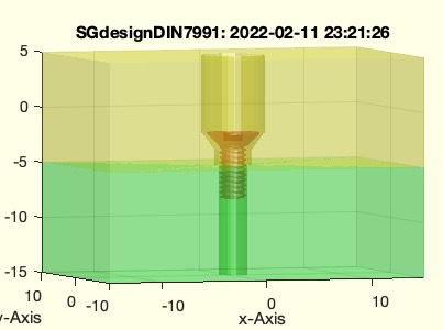 | % SGdesignDIN7991(sdl,tpl,nut) - creates a an assemly methods for DIN7991 or DIN965 % (by Tim Lueth, VLFL-Lib, 2022-FEB-10 as class: AUTOMATIC DESIGN) % % In the case of simple connection of 2 bodies by means of a screw % connection, where the rotation of the bodies in relation to each other % is to be maintained and due to the forces or speeds, which require % neither a radial nor an axial bearing, it is sufficient to place a % clearance fit around the screw and the screw head on the head side, % while at the foot end of the screw it is screwed into the plastic % material up to the stop. Alternatively, a self-locking nut (DIN985) or % an impact bushing can be used. However, if axial forces (pull-off or % push-in) do not occur, a simple self-tapping of the threads into a core % bore with the foot end of the screw into the second body is sufficient % for only occasional twisting tasks of the twill. (Motivated by % Christoph Parhofer, who used this method for very small linkages) % (Status of: 2022-02-12) % % Introduced first in SolidGeometry 5.1 % % See also: SGdesignDIN912DIN985, SGdesignDIN912BushingE % % [H,N,S,mt,parts]=SGdesignDIN7991([sdl,tpl,nut]) % === INPUT PARAMETERS === % sdl: [M-Screw Length overlength and spacer]; default [2.5 6 0 0] % tpl: expected overleng to achieve a through hole instead of a blind % hole ; default is 40 % nut: 'none' or 'bushing' or 'nut' on foot side; not implemented yet % === OUTPUT RESULTS ====== % H: Subtraction solid for head side including frame C to align on head % side % N: Subtraction solid for nut side including frame C to align on foot % side % S: Geometric Model of a inbus screw DIN 7991/965 with frame C to align % on head side % mt: remaining wall thickness % parts: parts list for assembly of one connection, just a screw % % EXAMPLE: % [H,N,S]=SGdesignDIN7991([8 10 0 0]) % B=SGsubtract(SGbox,N,'alignT',{'C','B'}); % A=SGsubtract(SGbox,H,'alignT',{'C','B'}); % SGfigure(-30,30); % SGplotalpha(A,'y',0.5); % SGplotalpha(B,'g',0.5,'',A,'alignT',{'B','B'}); % SGplotalpha(S,'r',1,'',A,'alignT',{'C','B'}); % % % See also: SGdesignDIN912DIN985, SGdesignDIN912BushingE % % % Copyright 2022 Tim C. Lueth |
CPLunionTL(CPL1,TL1,CPL2,TL2,buf)- adds a moving contour to another moving contour |
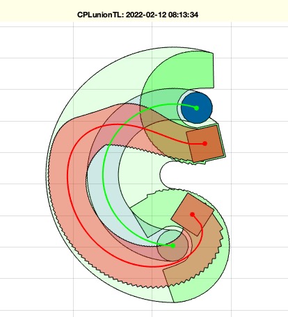 | % CPLunionTL(CPL1,TL1,CPL2,TL2,buf) - adds a moving contour to another moving contour % (by Tim Lueth, VLFL-Lib, 2022-FEB-10 as class: KINEMATICS AND FRAMES) % % helpful for any piano mover problem (Status of: 2022-02-10) % % Introduced first in SolidGeometry 5.1 % % See also: CPLsweepTL, CPLanimateTL, CPLsubtractTL % % CPLN=CPLunionTL([CPL1,TL1,CPL2,TL2,buf]) % === INPUT PARAMETERS === % CPL1: Contour to add to from % TL1: Contour to be added % CPL2: path of contour 1 must have the same length of TL2 or 3x3 % TL2: path of contour 2 must have the same length of TL1 or 3x3 % buf: buffer to increase CPL2 before start % === OUTPUT RESULTS ====== % CPLN: New contour % % EXAMPLE: % Posesample(10); PS=ans; % fourBarposesyntheses(Posesample(10),[2 3 4],[10 1 1]); PS=ans; % fourBarposeCPLmotion(PS,1); [PL0,TL0,wcr,TA1,TB1,TA0,TB0]=fourBarposeCPLmotion(PS,1); % CPLunionTL(PLcircle(5),TA1,PLsquare(5),TL0,2); CPLN=ans; % CPLsubtractTL(PLcircle(5),TA1,PLsquare(2),TL0,0.1); CPLN=ans; % % See also: CPLsweepTL, CPLanimateTL, CPLsubtractTL % % % Copyright 2022 Tim C. Lueth |
fourBarposesortsolution(PS,cmd,lim)- sorts the solutions of the fourbar struct by some criteria and even selects |
 | % fourBarposesortsolution(PS,cmd,lim) - sorts the solutions of the fourbar struct by some criteria and even selects % (by Tim Lueth, VLFL-Lib, 2022-FEB-10 as class: KINEMATICS AND FRAMES) % % SGfindswitchcaseconditions('fourBarposesortsolution'); % ground-length: Distance from A0 to B0 % crank-length: Distance from A0 to A1 % swing-length: Distance from B0 to B1 % coupler-length: Distance from A1 to B1 % flip: Change sort order % path-rotation: Rotation angle change along the pose path % path-length: Pose track length % path-area: Enclosed area of the pose track % path-stretch: Area to length ratio % base-posy: x-coordinate of the rack points % base-posy: y-coordinate of the rack points % base-CPLW: Base points outside CPLW % base-CPLM: Base points within CPLM % CPLE-CPLW: remaining area CPLE after subtraction of CPLW % % (Status of: 2022-03-02) % % Introduced first in SolidGeometry 5.1 % % See also: fourBarposeplotsolution, fourBarCLLL2SGdesign, % fourBarposelayering % % [PS,kk]=fourBarposesortsolution(PS,[cmd,lim]) % === INPUT PARAMETERS === % PS: Pose with field "solution" % cmd: command list such as 'path-stretch', [limits], % lim: limitationa % === OUTPUT RESULTS ====== % PS: Pose with sorted or selected poses % kk: last used and sorted criteria % % EXAMPLE: Posesample(10); PS=ans; % fourBarposesyntheses(Posesample(10),[2 3 4],[10 1 1]); PS=ans; % fourBarposeCPLmotion(PS,1); [PL0,TL0,wcr,TA1,TB1,TA0,TB0]=fourBarposeCPLmotion(PS,1); % fourBarposesyntheses(Posesample(10),[2 3 4],[20 1 1]); PS=ans; % fourBarposesortsolution(PS,'crank-length') % fourBarposesortsolution(PS,'path-length') % fourBarposesortsolution(PS,{'coupler-length',[18 60],'swing-length',[18 60],'crank-length',[10 60],'path-stretch',[0 2],'path-length',[100 inf]}); PSX=ans % % See also: fourBarposeplotsolution, fourBarCLLL2SGdesign, % fourBarposelayering % % % Copyright 2022 Tim C. Lueth |
jarvisunits(args)- parses the list of arguments, try to interprete last argument as unit |
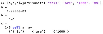 | % jarvisunits(args) - parses the list of arguments, try to interprete last argument as unit % (by Tim Lueth, VLFL-Lib, 2022-FEB-07 as class: USER INTERFACE) % % Introduced first in SolidGeometry 5.1 % % See also: jarvisgrammar % % [fact,mayu,newvar]=jarvisunits([args]) % === INPUT PARAMETERS === % args: list of arguments % === OUTPUT RESULTS ====== % fact: factor for multiplication such as 1e-3 for 'm' or 1e3 for 'k' % mayu: unit % newvar: new varargin list % % EXAMPLE: % jarvisunits this are 1000 mm % [a,b,c]=jarvisunits( 'this', 'are', '1000', 'mm') % % % See also: jarvisgrammar % % % Copyright 2022 Tim C. Lueth |
SGofR12(R12,DIN)- creates a solid to show the minimal solid size for assembly methods |
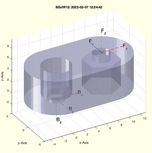 | % SGofR12(R12,DIN) - creates a solid to show the minimal solid size for assembly methods % (by Tim Lueth, VLFL-Lib, 2022-FEB-07 as class: KINEMATICS AND FRAMES) % % Introduced first in SolidGeometry 5.1 % % See also: SGofR12, R12ofM, plotannotationSG % % [SG,RMHL]=SGofR12([R12,DIN]) % === INPUT PARAMETERS === % R12: Dimensions of a link % DIN: if true; the fnctn SGdesignDIN912DIN985is used; default is false % === OUTPUT RESULTS ====== % SG: Solid of this link % RMHL: Minimal Dimensions % % EXAMPLE: % SGofR12([5 2.5 4]) % SGofR12([5 2.5 4],true) % % See also: SGofR12, R12ofM, plotannotationSG % % % Copyright 2022 Tim C. Lueth |
plotannotationSG(SG,)- plots a solid into the upper right corner of the current graphics axis |
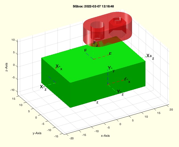 | % plotannotationSG(SG,) - plots a solid into the upper right corner of the current graphics axis % (by Tim Lueth, VLFL-Lib, 2022-FEB-07 as class: VISUALIZATION) % % In some cases it is interesting to see a reference body in the picture % for a size comparison. In the case of four-bar joints, for example, the % small technically feasible link of a four-bar joint with known assembly % method (Status of: 2022-02-07) % % Introduced first in SolidGeometry 5.1 % % See also: plotannotation, SGofR12 % % h=plotannotationSG(SG,[]) % === INPUT PARAMETERS === % SG: Solid Geometry % === OUTPUT RESULTS ====== % h: handle % % EXAMPLE: % SGbox; plotannotationSG(SGofR12([5 2.5 6])) % % See also: plotannotation, SGofR12 % % % Copyright 2022 Tim C. Lueth |
R12ofM(M,w)- returns the minimal dimensions of a link for a screw nut connection |
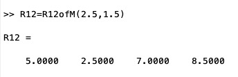 | % R12ofM(M,w) - returns the minimal dimensions of a link for a screw nut connection % (by Tim Lueth, VLFL-Lib, 2022-FEB-07 as class: PARAMETRIC DESIGN) % % Introduced first in SolidGeometry 5.1 % % See also: SGofR12 % % [RMHL,SG]=R12ofM([M,w]) % === INPUT PARAMETERS === % M: Metric size of screw % w: wall dimension; default is 1.25 % === OUTPUT RESULTS ====== % RMHL: [Radius M-screw Height Length] % SG: optional solid geometry % % EXAMPLE: % R12=R12ofM(2.5,1.5) % % See also: SGofR12 % % % Copyright 2022 Tim C. Lueth |
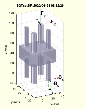
SGTsetBFsimple(SG,PL,az)- adds base frame and follower frame to a solid |
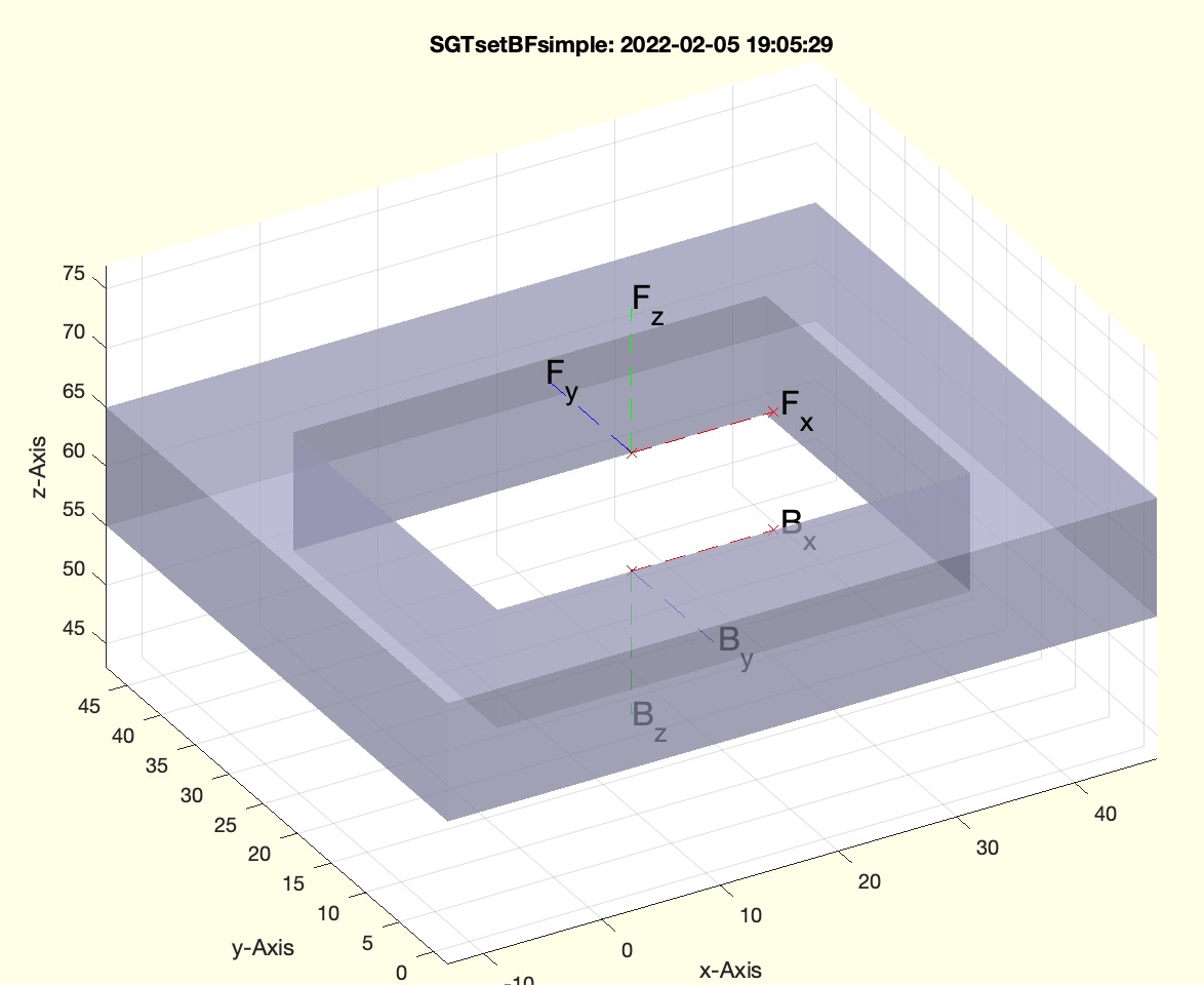 | % SGTsetBFsimple(SG,PL,az) - adds base frame and follower frame to a solid % (by Tim Lueth, VLFL-Lib, 2022-FEB-05 as class: KINEMATICS AND FRAMES) % % Introduced first in SolidGeometry 5.1 % % See also: SGTset, SGTsetBF % % SGN=SGTsetBFsimple(SG,[PL,az]) % === INPUT PARAMETERS === % SG: Solid Geometry % PL: xy position of centers; default is center of BB % az: optional rotation % === OUTPUT RESULTS ====== % SGN: Solid Geometry including base frame and follower frame % % EXAMPLE: % SGTsetBFsimple(SGtransP(SGsample(4),[17 23 55])) % PL=[0 0; 30 10], SGTsetBFsimple(SGofCPLz(CPLcopypatternPL(PLcircle(5),PL),5),PL) % % See also: SGTset, SGTsetBF % % % Copyright 2022 Tim C. Lueth |
fourBarCLLL2SGdesign_01(CLLL,R12,RACK,"layer","debug","bushing","assembly")- Converts a contour layered link list into a real solid geometry construction to 3D print |
 | % fourBarCLLL2SGdesign_01(CLLL,R12,RACK,"layer","debug","bushing","assembly") - Converts a contour layered link list into a real solid geometry construction to 3D print % (by Tim Lueth, VLFL-Lib, 2022-FEB-05 as class: KINEMATICS AND FRAMES) % % ======================================================================= % OBSOLETE (2022-02-23) - USE 'fourBarCLLL2SGdesign' INSTEAD % ======================================================================= % % The Contour Layer Link List has the following order % [CPLE;CPLC;CPLS;CPLG;CPLW;CPLA0;CPLB0;CPLA1;CPLB1] % Each cell list row of this 9x5 cell list has the format % {Name, CPL, TL, col, [Lmin lmax]} % This fnctn does not check collisions, but simply extrudes the bodies % and constructs the assembly method % The process: % Posesample => Posedefiniton % fourBarposesyntheses => compute fourbars % fourBarposeplotsolution => plot or animate solutions % fourBarposelayering => layer and compute shape % fourBarCLLL2SGdesign => Design for assembly and 3D print (Status of: % 2022-02-22) % % Introduced first in SolidGeometry 5.1 % % See also: [ fourBarCLLL2SGdesign ] ; Posesample, fourBarposesyntheses, % fourBarposeplotsolution, fourBarposelayering, fourBarCLLL2SGdesign % % [SG,SLLL]=fourBarCLLL2SGdesign_01(CLLL,[R12,RACK,"layer","debug","bushi % ng","assembly"]) % === INPUT PARAMETERS === % CLLL: contour layered link list % R12: [Ro Ri H]; default is 5 2.5 6] % RACK: Additional Rack Points for Fixation % "layer": % "debug": % "bushing": % "assembly": % === OUTPUT RESULTS ====== % SG: Cell list of Solid Gemetries % SLLL: Same as CLLL but with SGs instead of CPLs % % EXAMPLE: % % fourBarCLLL2SGdesign(LLLM), shg % [a,b]=fourBarCLLL2SGdesign(LLLM,'layer',[0 1 1 2]), shg % EXTREME RISKY TO MODIFY THE LAYERING % for i=1:size(SLLL,1); SGplotalpha(SGtransT(SLLL{i,2},T3ofT2(SLLL{i,3}(:,:,1)))); end; rotate3d on; % % % See also: [ fourBarCLLL2SGdesign ] ; Posesample, fourBarposesyntheses, % fourBarposeplotsolution, fourBarposelayering, fourBarCLLL2SGdesign % % % Copyright 2022 Tim C. Lueth |
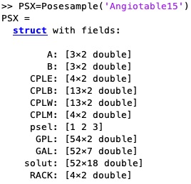
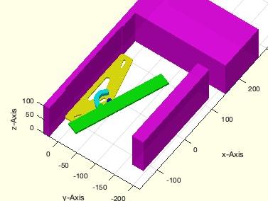
exp_2022_02_04_Layering(PSX,aps,lay,R12)- EXPERIMENT TO UNDERSTAND THE COMPLEXITY OF LAYERING A LINKAGE |
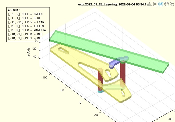 | % exp_2022_02_04_Layering(PSX,aps,lay,R12) - EXPERIMENT TO UNDERSTAND THE COMPLEXITY OF LAYERING A LINKAGE % (by Tim Lueth, VLFL-Lib, 2022-FEB-04 as class: EXPERIMENTS) % % THis experiment is to finish the research of exp_2022_01_28_Layering % Used to design different version of a fourbar linkage with exactly the % same kinematic motion but with different layered links. % (Status of: 2022-02-04) % % Introduced first in SolidGeometry 5.1 % % See also: jarvis, exp_2022_01_28_Layering % % SG=exp_2022_02_04_Layering([PSX,aps,lay,R12]) % === INPUT PARAMETERS === % PSX: Pose struct including "solut" field % aps: solution number % lay: layering; currently only used for assembly, motion is fixed to [0 % 2 1 1] % R12: Radius for the links % === OUTPUT RESULTS ====== % SG: Final solid geometry % % EXAMPLE: % PSX=Posesample('Angiotable15'); % exp_2022_02_04_Layering(PSX,15,[0 2 1 1]) % exp_2022_02_04_Layering(PSX,15,[0 2 1 -11]) % exp_2022_02_04_Layering(PSX,15,[0 2 1 -1]) % Videoquickstart; PML=permutevector([0],[2],[-2 -1 1 3 4],[-2 -1 1 3 4]); for i=1:size(PML,1); exp_2022_02_04_Layering(PSX,15,PML(i,:)); end; Videoquickcloseandopen; % % % See also: jarvis, exp_2022_01_28_Layering % % % Copyright 2022 Tim C. Lueth |
layerspacerlength(se,lay,R12,H)- returns the levels of the spacer for collision avoidance and shaping |
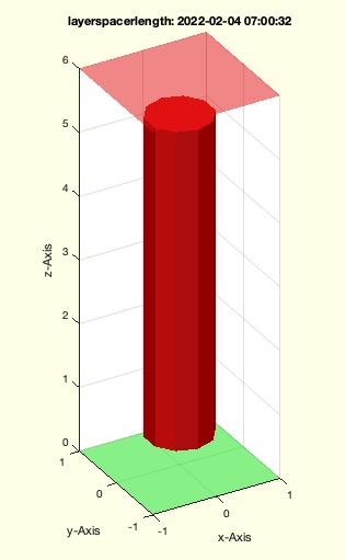 | % layerspacerlength(se,lay,R12,H) - returns the levels of the spacer for collision avoidance and shaping % (by Tim Lueth, VLFL-Lib, 2022-FEB-03 as class: KINEMATICS AND FRAMES) % % helful to prepare the full link links including spacer for % CPLsubtractTLasSG (Status of: 2022-02-03) % % Introduced first in SolidGeometry 5.1 % % See also: CPLsubtractTLasSG % % [ll,d,s]=layerspacerlength([se,lay,R12,H]) % === INPUT PARAMETERS === % se: [startindex-in-layers endindex-in-layers] % lay: [layer indices] default is [0 2 1 1] for ground, effector, crank % swing] % R12: just for visualization % H: just for visualization % === OUTPUT RESULTS ====== % ll: levels of spacer % d: length of spacer % s: direction of spacer % % EXAMPLE: % layerspacerlength([1 3],[0 4 6 8]) % layers and length of a spacer between layer 0 and layer 6 % layerspacerlength([1 3],[0 4 1 8]) % layers and length of a spacer between layer 0 and layer 1 % layerspacerlength([1 3],[0 4 0 8]) % layers and length of a spacer between layer 0 and layer 0 % layerspacerlength([1 3],[0 4 -6 8]) % layers and length of a spacer between layer 0 and layer -6 % % % See also: CPLsubtractTLasSG % % % Copyright 2022 Tim C. Lueth |
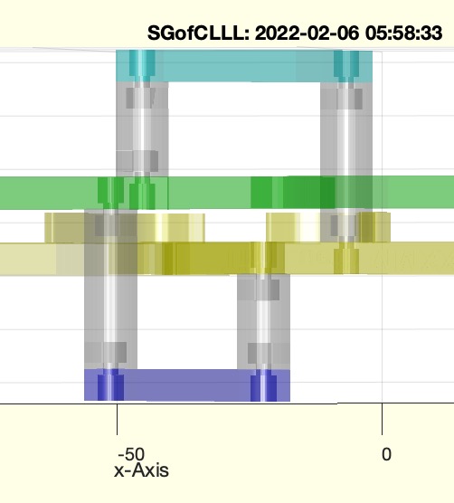
CPLsubtractTLasSG(LLLL,subc,,"h","WCR","debug")- collison based subtraction of moving contours |
 | % CPLsubtractTLasSG(LLLL,subc,,"h","WCR","debug") - collison based subtraction of moving contours % (by Tim Lueth, VLFL-Lib, 2022-FEB-03 as class: KINEMATICS AND FRAMES) % % Very powerful fnctn for fourBarposelayering (Status of: 2022-02-06) % % Introduced first in SolidGeometry 5.1 % % See also: layerspacerlength, CPLsubtract, CPLsubtractTL % % LLLN=CPLsubtractTLasSG(LLLL,subc,[,"h","WCR","debug"]) % === INPUT PARAMETERS === % LLLL: cell list {CPL1, TL1, Level1; CPL2, TL2, Level; ...} % subc: contour index row of the contour that is reduced % "h": optional for for graphical output => height % "WCR": optional for for graphical output => list of angles % "debug": if used; the individual steps are plotted % === OUTPUT RESULTS ====== % LLLN: List in which the cntour of subc ist modified by subtracting the % colliding contour in the same layer % % EXAMPLE: % Posesample(10); PS=ans; % fourBarposesyntheses(Posesample(10),[2 3 4],[10 1 1]); PS=ans; % fourBarposeCPLmotion(PS,1); [PL0,TL0,wcr,TA1,TB1,TA0,TB0]=fourBarposeCPLmotion(PS,1); % CPLunionTL(PLcircle(5),TA1,PLsquare(5),TL0,2); CPLN=ans; % CPLsubtractTL(PLcircle(5),TA1,PLsquare(2),TL0,0.1); CPLN=ans; % % See also: layerspacerlength, CPLsubtract, CPLsubtractTL % % % Copyright 2022 Tim C. Lueth |
note(fname,create)- opens a text file with a keyword in the matlab editor |
 | % note(fname,create) - opens a text file with a keyword in the matlab editor % (by Tim Lueth, VLFL-Lib, 2022-FEB-02 as class: APPLICATION) % % I wrote this feature because the use of Word and even Textedit clearly % significantly impede the flow of thought when writing due to the user % interface and formatting, which I am simply not willing to accept % because it makes people intellectually inefficient due to constant % distraction. Spelling and style correction is now handled by DeepL. % (Status of: 2022-02-02) % % Introduced first in SolidGeometry 5.1 % % See also: openinmatlabeditor, https://www.deepl.com % % note([fname,create]) % === INPUT PARAMETERS === % fname: keyword used as filename later % create: if true, the file will be created if not existing already % % EXAMPLE: % note jarvis true % Opens a file if not existing already % note jarvis % Opens the file (if existing) or recommends existing keywords % % See also: openinmatlabeditor, https://www.deepl.com % % % Copyright 2022 Tim C. Lueth |
Posesampleupdate(Name,PS,repl)- inserts a pose struct and a name into the posesamles.mat file |
 | % Posesampleupdate(Name,PS,repl) - inserts a pose struct and a name into the posesamles.mat file % (by Tim Lueth, VLFL-Lib, 2022-FEB-02 as class: KINEMATICS AND FRAMES) % % The fnctn Posesample can be called using a number or a string. In case % of useing Posesample with a string, the file Posesamles.mat is loaded % tht containt the cell list Posesamples which is simple a list of type % {Name, Struct} % This fnctn allowes at any time to add or update a struct with a name % into this table, and therfor aftwre to get this struxt using % Posesample( % % Introduced first in SolidGeometry 5.1 % % See also: Posesample % % new=Posesampleupdate(Name,PS,[repl]) % === INPUT PARAMETERS === % Name: Name to be used by Posesample( % PS: Pose struct % repl: true if it should be replaced if existing already % === OUTPUT RESULTS ====== % new: true if added % % EXAMPLE: % PSX=jarvismemory % Posesampleupdate('Angiotable15',PSX,15) % % See also: Posesample % % % Copyright 2022 Tim C. Lueth |
CPLanimateTLasSG(cnam,cset,"h","WCR")- generic fnct to animate a set of contour on indivual pathes as 2.5 layered solid geometries |
 | % CPLanimateTLasSG(cnam,cset) - generic fnct to animate a set of contour on indivual pathes as 2.5 layered solid geometries % (by Tim Lueth, VLFL-Lib, 2022-FEB-01 as class: KINEMATICS AND FRAMES) % % CPL has format [n x 2 ] % CPL separated by % TL format has [3 x 3 x m] % m frames % col format as standard 'r', 'c', % lev format as [min max] such as [0 1] for used level 1 and 2 % More generic but not as interactive yet as fourBarposeplotsolution, % Poseplotsolution, PLofFourbarcouplercurve, which are all based on % fourBarLinkageplotanimui % % 'WCR' is optional angle list % 'h' is parameter for height of level % % Automatically detects collisions (Status of: 2022-02-02) % % Introduced first in SolidGeometry 5.1 % % See also: CPLplot % % h=CPLanimateTLasSG([cnam,cset]) % === INPUT PARAMETERS === % cnam: string name of contour % cset: cell list of {CPL, TL-HT-array, colstrm [lmin lmax]}; such as % [PLsquare(10), TL, 'r' such as [0 1] % === OUTPUT RESULTS ====== % h: handle to last plot % % EXAMPLE: % cla; CPLanimateTL('CPLE',{CPLE,TL0},'CPLS',{CPLS,TB1},'CPLC',{CPLC,TA1},'CPLW',{PSX.CPLW,'','r'}) % CPLanimateTLasSG('CPLE',{CPLE,TL0,'g',2},'CPLS',{CPLS,TB1,'c',1},'CPLC',{CPLC,TA1,'b',3},'CPLG',{CPLG,'','y',0},'CPLW',{CPLsubtract(PSX.CPLW,CPLG),'','',0}); % % See also: CPLplot % % % Copyright 2022 Tim C. Lueth |
CPLtransrelT(CPL,TA1,TA0)- transform the pose of a CPL from one coordinate system into another |
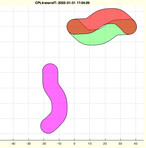 | % CPLtransrelT(CPL,TA1,TA0) - transform the pose of a CPL from one coordinate system into another % (by Tim Lueth, VLFL-Lib, 2022-JAN-31 as class: KINEMATICS AND FRAMES) % % educational fnctn (Status of: 2022-01-31) % % Introduced first in SolidGeometry 5.1 % % See also: CPLanimateTL % % [CPLN,T]=CPLtransrelT(CPL,TA1,TA0) % === INPUT PARAMETERS === % CPL: Contour for instance a crank % TA1: 2D Frame or Frame list for example the path of the crank point A1 % TA0: 2D Frame or Frame list for example the path of the crank origin % point A0 % === OUTPUT RESULTS ====== % CPLN: Contour to be move using TA0 % T: Transformation matrix to covert CPL to CPLN % % EXAMPLE: % CPLtransrelT(CPLC,TA1,TA0); % % See also: CPLanimateTL % % % Copyright 2022 Tim C. Lueth |
CPLfourbarblockswing(CPLG,CPLC,TA1,CPLS,TB1,buff,A0B0)- creates the contour that limit the swing movement |
 | % CPLfourbarblockswing(CPLG,CPLC,TA1,CPLS,TB1,buff,A0B0) - creates the contour that limit the swing movement % (by Tim Lueth, VLFL-Lib, 2022-JAN-31 as class: KINEMATICS AND FRAMES) % % will may be change the name (Status of: 2022-01-31) % % Introduced first in SolidGeometry 5.1 % % See also: exp_2022_01_28_Layering % % CPLBlock=CPLfourbarblockswing(CPLG,CPLC,TA1,CPLS,TB1,[buff,A0B0]) % === INPUT PARAMETERS === % CPLG: Unmoved contour (Ground Links) % CPLC: Contour of Cranc % TA1: Motion path of Cranc % CPLS: Contour of Swing % TB1: Motion path of Swing % buff: [width of block, slot, radius for A0/B0]; default is [3 0.5 20] % A0B0: Point list of A0 and B0 that limits the size of the block with % buff(3) % === OUTPUT RESULTS ====== % CPLBlock: Contour of Block to add to CPLG % % EXAMPLE: % CPLfourbarblockswing(CPLG,CPLC,TA1,CPLS,TB1,[3 0.5]); % CPLfourbarblockswing(CPLG,CPLC,TA1,CPLS,TB1,[3 0.5 20],[A0;B0]); % % See also: exp_2022_01_28_Layering % % % Copyright 2022 Tim C. Lueth |
SGTsetBF(SG,varargin,"new")- set frames 'B' and 'F' at default positions |
 | % SGTsetBF(SG,varargin,"new") - set frames 'B' and 'F' at default positions % (by Tim Lueth, VLFL-Lib, 2022-JAN-31 as class: KINEMATICS AND FRAMES) % % Should be used only for fast tests. Postion ist not precise +/- 0.01mm. % While SGTsetBFsimple uses the dimensions of the Bounding box, this % fnctn SGTsetBF uses feature surfaces to detect the desired orthogonal % vectors/ The alpha values is pi/4 for accepting a fitting surface % (Status of: 2022-02-07) % % Introduced first in SolidGeometry 5.1 % % See also: SGTset, SGTsetBFsimple % % [SGN,T]=SGTsetBF(SG,[varargin,"new"]) % === INPUT PARAMETERS === % SG: Solid Geometry without Frames Frames 'B' and 'F' % varargin: List of Frames to add; default is varargin={'B',[0 0 % -1],'F',[0 0 1]}; % "new": % "new": % === OUTPUT RESULTS ====== % SGN: Solid with Frames 'B' and 'F' % T: T matrix % % EXAMPLE: % SGTsetBF(SGtransR(SGsample(4),rot(pi/10,pi/10,0),[17 23 55])) % SGTsetBF(SGTremove(SGsample(5),'all')) % SGTsetBF(SGTremove(SGsample(16),'all')) % SGTsetBF(SGTremove(SGsample(52),'all')) % % See also: SGTset, SGTsetBFsimple % % % Copyright 2022 Tim C. Lueth |
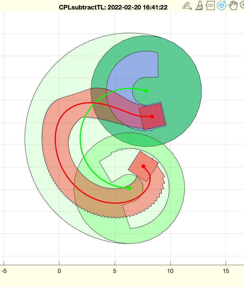
CPLsubtractTL(CPL1,TL1,CPL2,TL2,buf)- subtract a moving contour from another moving contour |
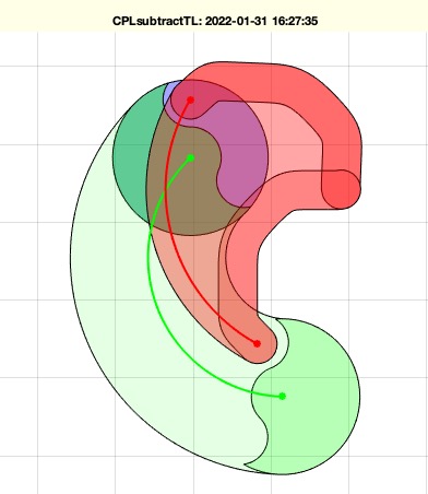 | % CPLsubtractTL(CPL1,TL1,CPL2,TL2,buf) - subtract a moving contour from another moving contour % (by Tim Lueth, VLFL-Lib, 2022-JAN-30 as class: KINEMATICS AND FRAMES) % % helpful for any piano mover problem (Status of: 2022-02-12) % % Introduced first in SolidGeometry 5.1 % % See also: CPLsweepTL, CPLanimateTL, CPLunionTL % % CPLN=CPLsubtractTL([CPL1,TL1,CPL2,TL2,buf]) % === INPUT PARAMETERS === % CPL1: Contour to subtract from % TL1: Contour to be subtracted % CPL2: path of contour 1 must have the same length of TL2 or 3x3 % TL2: path of contour 2 must have the same length of TL1 or 3x3 % buf: buffer to increase CPL2 before start % === OUTPUT RESULTS ====== % CPLN: New contour % % EXAMPLE: % Posesample(10); PS=ans; % fourBarposesyntheses(Posesample(10),[2 3 4],[10 1 1]); PS=ans; % fourBarposeCPLmotion(PS,1); [PL0,TL0,wcr,TA1,TB1,TA0,TB0]=fourBarposeCPLmotion(PS,1); % CPLunionTL(PLcircle(5),TA1,PLsquare(5),TL0,2); CPLN=ans; % CPLsubtractTL(PLcircle(5),TA1,PLsquare(2),TL0,0.1); CPLN=ans; % % See also: CPLsweepTL, CPLanimateTL, CPLunionTL % % % Copyright 2022 Tim C. Lueth |
CPLsweepTL(CPL,TL)- returns the contour of a path swept contour |
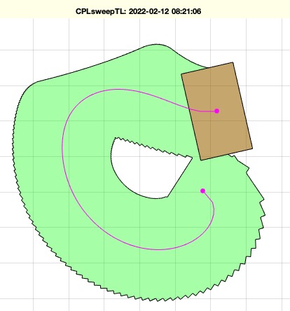 | % CPLsweepTL(CPL,TL) - returns the contour of a path swept contour % (by Tim Lueth, VLFL-Lib, 2022-JAN-30 as class: CLOSED POLYGON LISTS) % % Slow but necessary (Status of: 2022-02-12) % % Introduced first in SolidGeometry 5.1 % % See also: CPLsweep, CPLanimateTL, CPLunionTL, CPLsubtractTL % % CPLS=CPLsweepTL(CPL,TL) % === INPUT PARAMETERS === % CPL: Contour with Center % TL: HT list [3 x 3 x n] with n frames % === OUTPUT RESULTS ====== % CPLS: CPLunion of all transformed CPLs % % EXAMPLE: % Posesample(10); PS=ans; % fourBarposesyntheses(Posesample(10),[2 3 4],[10 1 1]); PS=ans; % fourBarposeCPLmotion(PS,1); [PL0,TL0,wcr,TA1,TB1,TA0,TB0]=fourBarposeCPLmotion(PS,1); % CPLsweepTL(PLsquare(5,3),TL0); CPLN=ans; % % % See also: CPLsweep, CPLanimateTL, CPLunionTL, CPLsubtractTL % % % Copyright 2022 Tim C. Lueth |
colorname(cs,num)- returns a name for a color string or a cell list of colstrings |
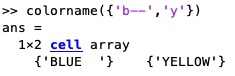 | % colorname(cs,num) - returns a name for a color string or a cell list of colstrings % (by Tim Lueth, VLFL-Lib, 2022-JAN-30 as class: VISUALIZATION) % % Introduced first in SolidGeometry 5.1 % % See also: colofn, colofPose, nofcolmap % % cname=colorname(cs,[num]) % === INPUT PARAMETERS === % cs: color such such as 'r--', or {'r--','b.-'} % num: length of format; 0 is automatic % === OUTPUT RESULTS ====== % cname: string or cell list of strings % % EXAMPLE: % colorname({'b--','y'},3) % % See also: colofn, colofPose, nofcolmap % % % Copyright 2022 Tim C. Lueth |
CPLanimateTL(cnam,cset)- generic fnct to animate a set of contour on indivual pathes |
 | % CPLanimateTL(cnam,cset) - generic fnct to animate a set of contour on indivual pathes % (by Tim Lueth, VLFL-Lib, 2022-JAN-30 as class: KINEMATICS AND FRAMES) % % CPL has format [n x 2 ] % CPL separated by % TL format has [3 x 3 x m] % m frames % col format as standard 'r', 'c', % % More generic but NOT as powerful yet as fourBarposeplotsolution, % Poseplotsolution, PLofFourbarcouplercurve, which are all based on % fourBarLinkageplotanimui % % (Status of: 2022-02-01) % % Introduced first in SolidGeometry 5.1 % % See also: CPLplot, fourBarLinkageplotanimui % % h=CPLanimateTL([cnam,cset]) % === INPUT PARAMETERS === % cnam: string name of contour % cset: cell list of {CPL, TL-HT-array, colstr}; such as [PLsquare(10), % TL, 'r'] % === OUTPUT RESULTS ====== % h: handle to last plot % % EXAMPLE: % cla; CPLanimateTL('CPLE',{CPLE,TL0},'CPLS',{CPLS,TB1},'CPLC',{CPLC,TA1},'CPLW',{PSX.CPLW,'','r'}) % SGfigure; CPLanimateTL('CPLE',{CPLE,TL0},'CPLS',{CPLS,TB1},'CPLC',{CPLC,TA1},'CPLW',{PSX.CPLW,'','m'},'WCR',(0:pi/119:pi)/pi*180); h=ans; % % See also: CPLplot, fourBarLinkageplotanimui % % % Copyright 2022 Tim C. Lueth |
axis4animation(defax)- automatically increases but never decreases the axis area |
 | % axis4animation(defax) - automatically increases but never decreases the axis area % (by Tim Lueth, VLFL-Lib, 2022-JAN-30 as class: VISUALIZATION) % % Call it once with intial parameters such as axis4animation([0 1 0 1]); % % the use it before drawnowvid or drawnow (Status of: 2022-03-29) % % Introduced first in SolidGeometry 5.1 % % See also: CPLanimationTL, axis4math, drawnowvid, drawnow, axisratio, % axisscale % % nx=axis4animation([defax]) % === INPUT PARAMETERS === % defax: initial values to set % === OUTPUT RESULTS ====== % nx: current axis values % % EXAMPLE: axis4animation([0 1 0 1]); % for i=steps % delete(h); % h=[h;PSplot(PLtransT(CPLE,TL0(:,:,i)),colofPose('E'))]; % axis4animation % drawnowvid; % end % % % See also: CPLanimationTL, axis4math, drawnowvid, drawnow, axisratio, % axisscale % % % Copyright 2022 Tim C. Lueth |
SGTcylinder(r,h)- same as SGcylinder bu including frames |
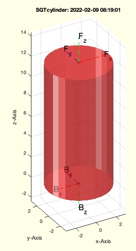 | % SGTcylinder(r,h) - same as SGcylinder bu including frames % (by Tim Lueth, VLFL-Lib, 2022-JAN-30 as class: PARAMETRIC DESIGN) % % ======================================================================= % OBSOLETE (2022-02-09) - USE 'SGTsetBF(SGcylinder)' INSTEAD % ======================================================================= % % May better is to use SGTSetB or SGTsetBFsimple(SGcylinder,[0 0]) % (Status of: 2022-02-09) % % Introduced first in SolidGeometry 5.1 % % SG=SGTcylinder([r,h]) % === INPUT PARAMETERS === % r: % h: % === OUTPUT RESULTS ====== % SG: % % % Copyright 2022 Tim C. Lueth |
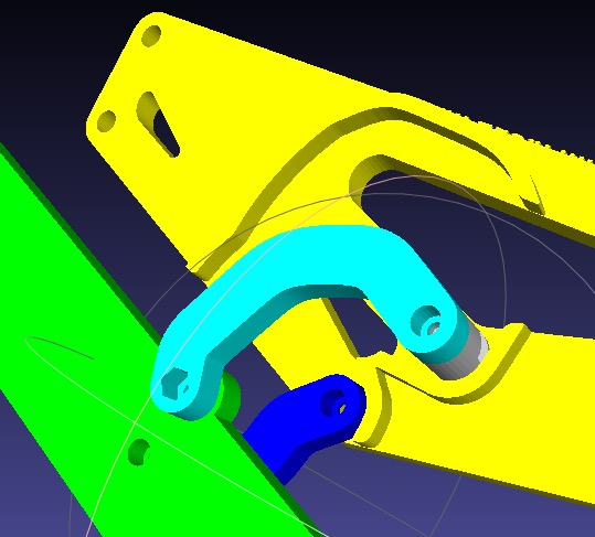
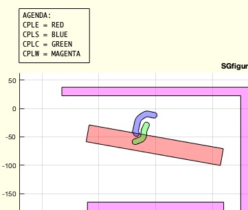
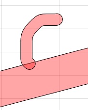
colofPose(cs4Bar)- returs colors from Pose and 4Bar standard colors |
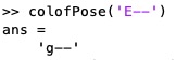 | % colofPose(cs4Bar) - returs colors from Pose and 4Bar standard colors % (by Tim Lueth, VLFL-Lib, 2022-JAN-29 as class: KINEMATICS AND FRAMES) % % 4Bar link/area desciption letters and colors: % C Crank is blue % S Swing is cyan % E Effector is green % G Ground is yellow % 4bar area colors" % B Background is karbon % M Assembly are is blue % W Restricted are is red % (Status of: 2022-01-29) % % Introduced first in SolidGeometry 5.1 % % See also: nofcolmap, colofn % % cs=colofPose(cs4Bar) % === INPUT PARAMETERS === % cs4Bar: color string using 4Bar link/area desciption letters such as % 'E--' for effector dashed % === OUTPUT RESULTS ====== % cs: that uses standard Matlab colors such as 'r--' % % See also: nofcolmap, colofn % % % Copyright 2022 Tim C. Lueth |
fourbarposeCPLshaping(PS,aps,CPL,att,XCPLW,XCPLE,XCPLC,XCPLS,LEVEL,"R12","debug")- returns collision free path shaped contour for a specific fourbar linkage |
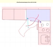 | % fourbarposeCPLshaping(PS,aps,CPL,att,XCPLW,XCPLE,XCPLC,XCPLS,LEVEL) - returns collision free path shaped contour for a specific fourbar linkage % (by Tim Lueth, VLFL-Lib, 2022-JAN-28 as class: MECHANICAL PROCEDURES) % % This is a new version of CPLofPosefourbarshaping of original % CPLofPosefourbarshaping of June-2019 % This is a full implementation of original Posefourbarshaping of April % 2019 (Status of: 2022-01-29) % % Introduced first in SolidGeometry 5.1 % % See also: exp_2022_01_28_Layering, exp_2019_04_16_Shape, % exp_2019_03_28_Shape, exp_2018_12_20_cuttingshape % % CPL=fourbarposeCPLshaping(PS,[aps,CPL,att,XCPLW,XCPLE,XCPLC,XCPLS,LEVEL % ]) % === INPUT PARAMETERS === % PS: Pose and fourbar linkage struct including GPL and GAL % aps: [solution, limiting order] % CPL: Contour to shape; if empty an simple contour is created % att: Given CPL is moved relatively/is attached to 'E'ffector, 'C'rank, % or 'Swing' or 'WORLD' % XCPLW: Static obstacles in the environment and will cut the moving CPL % XCPLE: Obstacle contours attached to Pose and will cut the moving CPL % XCPLC: Obstacle contour moved with crank and will cut the moving CPL % XCPLS: Obstacle contour moved with swing and will cut the moving CPL % === OUTPUT RESULTS ====== % CPL: Collision free contour % % EXAMPLE: % PosereadAPD('/Volumes/LUETH-WIN/MATLAB_files_for_experiments/basecabinet_new.APD');PS=ans; % PS=checkfourbar3Poseattachpermutation(PS,'',20) % PS.CPLE=CPLfillinside(PS.CPLE); % CPLofPosefourbarshaping(PS,[546]) % Full path of the fourbar % CPLofPosefourbarshaping(PS,[546,123]) % limited to poses 123 % %% TRY WITH 546 and 153 % CPLofPosefourbarshaping(PS,[546,123],'','E',''); PS.CPLE=ans; % Shape of effektor % CPLofPosefourbarshaping(PS,[546,123],'','C','',PS.CPLE); PS.CPLC=ans; % Shape of crank % CPLofPosefourbarshaping(PS,[546,123],'','S','',PS.CPLE,PS.CPLC); PS.CPLS=ans; % Shape of swing % CPLofPosefourbarshaping(PS,[546,123],'','W','',PS.CPLE,PS.CPLC,PS.CPLS); % Work Space % % % See also: exp_2022_01_28_Layering, exp_2019_04_16_Shape, % exp_2019_03_28_Shape, exp_2018_12_20_cuttingshape % % % Copyright 2022 Tim C. Lueth |
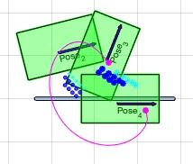
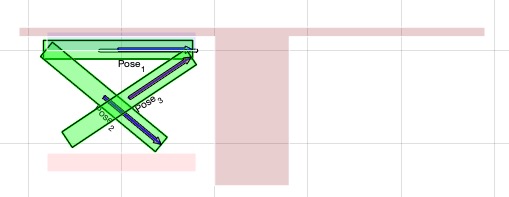
fourBarposeCPLmotion(PS,aps,npnt,att,CPL,"R12")- returns the motion of all parts of a fourbar linkage |
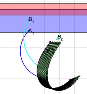 | % fourBarposeCPLmotion(PS,aps,npnt,att,CPL) - returns the motion of all parts of a fourbar linkage % (by Tim Lueth, VLFL-Lib, 2022-JAN-28 as class: KINEMATICS AND FRAMES) % % This fnctn has an educational code % 2022 version of PLofPosecouplercurve - much easier to read % % ==> fourBarposesyntheses <== (2021) % checkfourbar3Poseattachpermutation & checkfourbar123solutions % ==> fourBarposeplotsolution <== (2021) Poseplotsolution % ==> fourBarposeCPLmotion <== (2021) % PLofPosecouplercurve(PS,aps,np); % ==> fourbarposeCPLshaping <== (2021) CPLofPosefourbarshaping % ==> fourBarposelayering new in 2022 (Status of: 2022-01-28) % % Introduced first in SolidGeometry 5.1 % % See also: fourBarposesyntheses, fourBarposeplotsolution, % fourbarposeCPLshaping, fourBarposelayering % % [PL0,TL0,wcr,TA0,TB0,TA1,TB1]=fourBarposeCPLmotion(PS,[aps,npnt,att,CPL % ]) % === INPUT PARAMETERS === % PS: Pose with field "solut" % aps: solution number % npnt: number of points along the path % att: contour attached to "CPLP0", "CPLA0", "CPLB0", "CPLA1", "CPLB1"; % just for graphical output % % CPL: contour to attach; default is an arrow % === OUTPUT RESULTS ====== % PL0: Point list of pose movement % TL0: List of 3x3 HT of pose movement % wcr: corresponding angle list of cranc during motion % TA0: List of 3x3 HT of A0 movement % TB0: List of 3x3 HT of B0 movement % TA1: List of 3x3 HT of A1 movement % TB1: List of 3x3 HT of B1 movement % % EXAMPLE: % PSX=PosesampleCTFieldgenerator % PSX=fourBarposesyntheses(PSX,[1 2 3],[20 2 2]) % aps=2; % SGfigure; Poseplot(PSX); Poseplotspace(PSX); fourBarposeplotsolution(PSX,aps); % fourBarposeCPLmotion(PSX,aps); % % % See also: fourBarposesyntheses, fourBarposeplotsolution, % fourbarposeCPLshaping, fourBarposelayering % % % Copyright 2022 Tim C. Lueth |
siri2jarvis(str,fn)- converts spoken or written natural language sentences into a simple grammar |
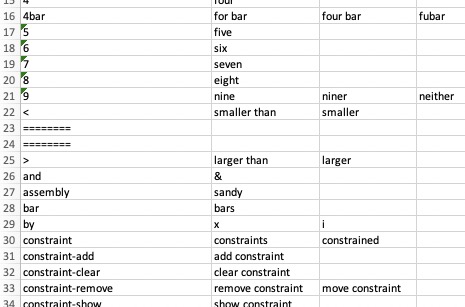 | % siri2jarvis(str,fn) - converts spoken or written natural language sentences into a simple grammar % (by Tim Lueth, VLFL-Lib, 2022-JAN-27 as class: USER INTERFACE) % % this funtion uses an excel sheet as translation table that can be % edited manually or by this fnctn itself. The fnctn will replace % siri2posecommand which is a hardcode version of this language converter. % The advantage of siri2jarvis is that the dictionary can simply % exchanged for different "application specific languages". This version % reads in the jarvisdictionary just before processing a line, this % allows to create the dictionary using excel just in parallel to the use % of the NL interface (Status of: 2022-01-27) % % Introduced first in SolidGeometry 5.1 % % See also: siri2jarvis, fourbardesignbysiri, jarvisdictionary % % [cmd,str,comtab]=siri2jarvis([str,fn]) % === INPUT PARAMETERS === % str: string to interprete % fn: filename of the dictionnary used % === OUTPUT RESULTS ====== % cmd: cell list of commands, the first is always a string % str: string that was finally processed % comtab: table of terminal words that were allowed as commands % % EXAMPLE: % while true; siri2jarvis, end; % test and train the translator % % See also: siri2jarvis, fourbardesignbysiri, jarvisdictionary % % % Copyright 2022 Tim C. Lueth |
jarvisdictionary(fname)- reads writes a excel sheet containing string to replace and code to execute |
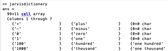 | % jarvisdictionary(fname) - reads writes a excel sheet containing string to replace and code to execute % (by Tim Lueth, VLFL-Lib, 2022-JAN-27 as class: USER INTERFACE) % % Used to modify the language interface jarvis during runtime % currently the dictinoary used only for translating. It is also possible % to use it as matlab fnctn execution system % SGwritetable(fname,array2tableTL(a,b{:}),c); (Status of: 2022-01-29) % % Introduced first in SolidGeometry 5.1 % % See also: siri2jarvis, SGwritetable, SGreadtable % % [fulltab,b,c]=jarvisdictionary([fname]) % === INPUT PARAMETERS === % fname: file name of the excel-sheet to use % === OUTPUT RESULTS ====== % fulltab: Table % b: names % c: comment lines % % See also: siri2jarvis, SGwritetable, SGreadtable % % % Copyright 2022 Tim C. Lueth |
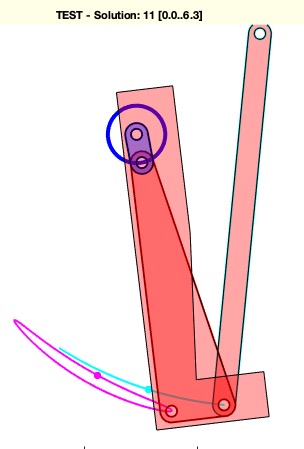
titleappend(txt)- appends a string to the gca title |
 | % titleappend(txt) - appends a string to the gca title % (by Tim Lueth, VLFL-Lib, 2022-JAN-27 as class: USER INTERFACE) % % Introduced first in SolidGeometry 5.1 % % See also: getgcatitle, title % % [h,old]=titleappend(txt) % === INPUT PARAMETERS === % txt: text to append % === OUTPUT RESULTS ====== % h: handle to title % old: old title before change % % EXAMPLE: % figure; % title ('TEST'); shg % titleappend ('NEW') % % % See also: getgcatitle, title % % % Copyright 2022 Tim C. Lueth |
PosesampleCTFieldgenerator- creates a sample to design a turnable field generator fixture |
 | % PosesampleCTFieldgenerator - creates a sample to design a turnable field generator fixture % (by Tim Lueth, VLFL-Lib, 2022-JAN-27 as class: KINEMATICS AND FRAMES) % % Introduced first in SolidGeometry 5.1 % % See also: Posesample, PosesampleCover, PosesampleWalk % % PS=PosesampleCTFieldgenerator % === OUTPUT RESULTS ====== % PS: % % EXAMPLE: % PosesampleCTFieldgenerator; PS=ans; % % See also: Posesample, PosesampleCover, PosesampleWalk % % % Copyright 2022 Tim C. Lueth |
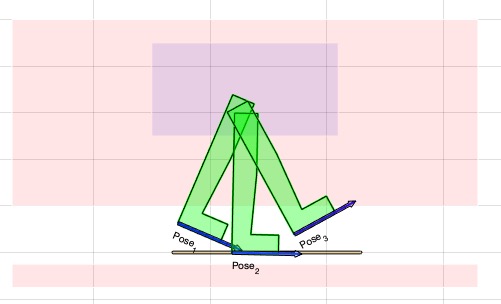
fourBarposeplotsolution(PS,aps,vis,num)- Standard procedure to animate fourBarposesyntheses results |
 | % fourBarposeplotsolution(PS,aps,vis,num) - Standard procedure to animate fourBarposesyntheses results % (by Tim Lueth, VLFL-Lib, 2022-JAN-27 as class: KINEMATICS AND FRAMES) % % manily same as Poseplotsolution - Next steps are CPLofPosefourbarshaping % The fnctn names changed in 2022 after integration of 1-, 2-, % 3-Posesythesis: % % ==> fourBarposesyntheses <== (2021) % checkfourbar3Poseattachpermutation & checkfourbar123solutions % ==> fourBarposeplotsolution => Select and sort solutions % ==> fourBarposeplotsolution <== (2021) Poseplotsolution % ==> fourBarposeCPLmotion <== (2021) % PLofPosecouplercurve(PS,aps,np); % ==> fourbarposeCPLshaping <== (2021) CPLofPosefourbarshaping % ==> fourBarposelayering => Layer and compute shape % ==> fourBarCLLL2SGdesign => Design for assembly and 3D print % (Status of: 2022-02-14) % % Introduced first in SolidGeometry 5.1 % % See also: fourBarposesyntheses, fourBarposelayering % % [h,oldtitle]=fourBarposeplotsolution([PS,aps,vis,num]) % === INPUT PARAMETERS === % PS: Pose struct include PS.solut field % aps: Single pose or selection of poses % vis: 'plot', 'animate', 'both' % num: number of solutions and delay time; default is [1000 -1]; negative % time requires interaction % === OUTPUT RESULTS ====== % h: handle to graphics % oldtitle: original axis title % % EXAMPLE: % PS=PosesampleWalk % PS=fourBarposesyntheses(PS,[1 2],[15 3 3],'','','isrot,break coll CPLW CPL0'); % 200 solutions % PS=fourBarposesyntheses(PS,[1 2],[20 2.5 2.5],'','','isrot,break coll CPLW CPL0'); % 317 solutions % fourBarposeplotsolution(PS,1); % Videoquickstart; SGfigure; Poseplotspace(PS); Poseplot(PS); fourBarposeplotsolution(PS,'','animate',[1000 1]); Videoquickcloseandopen; % long night video recording % % See also: fourBarposesyntheses, fourBarposelayering % % % Copyright 2022 Tim C. Lueth |
PLshortestpathinCPLcost(CPL,A,B,shr,n,smo,CPLG)- returns a path inside of a CPL using A* Zelinzky, Lozano-Perez, Dikstra |
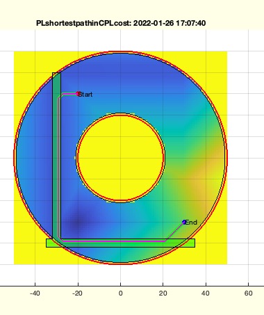 | % PLshortestpathinCPLcost(CPL,A,B,shr,n,smo,CPLG) - returns a path inside of a CPL using A* Zelinzky, Lozano-Perez, Dikstra % (by Tim Lueth, VLFL-Lib, 2022-JAN-26 as class: CLOSED POLYGON LISTS) % % EXTENDE VERSION OF PLshortestpathinCPL will be renamed % This fnctn is helpful not only for path planning in 2D but also to % define CPLs for Solids inside of a limiting contour between start and % endpoints (Base points, Attachment points) % read also the dissertation of Tim Lueth ;-) (Status of: 2022-02-10) % % Introduced first in SolidGeometry 5.1 % % See also: CPLofPLgrowline, PLshortestpathinCPL, CPLskeleton, % CPLskeletonsearch, matrixskeleton, matrixdistanceofCPL % % [PLB,PL,k,shr]=PLshortestpathinCPLcost(CPL,A,B,[shr,n,smo,CPLG]) % === INPUT PARAMETERS === % CPL: Outer contour with holes as forbidden areas % A: Starting Point A inside the CPL % B: End Point B inside the CPL % shr: shrinkage value; default is sofBB/n % n: number of grid points; default is 100 % smo: 'A*', 'Bezier', 'fft' for smoothening % CPLG: With this fnctn preferred paths can be defined % === OUTPUT RESULTS ====== % PLB: Bezier smoothed path % PL: Grid bases path % k: grid numbers % shr: dynamic shrinkage value % % EXAMPLE: % CPLunion(PLsquare(10,70)+[-30 0],PLsquare(70,10)+[0 -40]);CPLG=ans; % PLshortestpathinCPLcost(PLcircle([50 20]),[-30,-30],[30,-30],1,50,'A*',CPLG); % PLshortestpathinCPLcost(PLcircle([50 20]),[-30,-30],[30,+30],1,50,'A*',CPLG); % PLshortestpathinCPLcost(PLcircle([50 20]),[-20,-30],[30,-30],1,50,'A*',CPLG); % PLshortestpathinCPLcost(PLcircle([50 20]),[-20,+30],[30,-30],1,50,'a*',CPLG); % obstacle and pathway % PLshortestpathinCPLcost(PLcircle([50 20]),[-20,+30],[30,-30],1,50,'a*'); % without pathway % % See also: CPLofPLgrowline, PLshortestpathinCPL, CPLskeleton, % CPLskeletonsearch, matrixskeleton, matrixdistanceofCPL % % % Copyright 2022 Tim C. Lueth |
CPLrackPLdelaunaypath(PL,b,CPLW,CPLG)- same as CPLrackPLdelaunaypath, but allow forbidded areas |
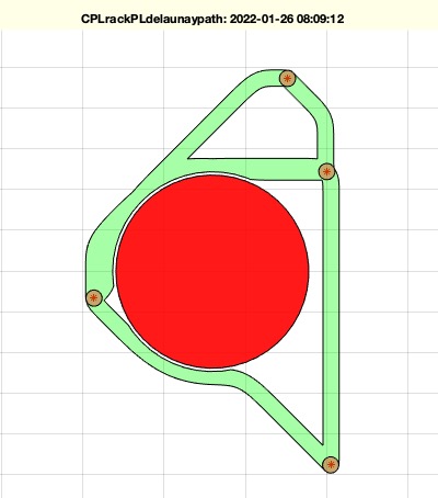 | % CPLrackPLdelaunaypath(PL,b,CPLW,CPLG) - same as CPLrackPLdelaunaypath, but allow forbidded areas % (by Tim Lueth, VLFL-Lib, 2022-JAN-26 as class: CLOSED POLYGON LISTS) % % ART DECO STYLE % used to define rack structures % Uses delaunay and not VLnearestNeighborN to avoid small angles % Uses PLshortestpathinCPL to implement the path planning for obstacle % avoidance (Status of: 2022-01-26) % % Introduced first in SolidGeometry 5.1 % % See also: CPLextendbyPL, CPLrack4PL, CPLrackPLdelaunay, % PLshortestpathinCPL % % CPL=CPLrackPLdelaunaypath([PL,b,CPLW,CPLG]) % === INPUT PARAMETERS === % PL: Point list % b: buffer size around PL % CPLW: Forbidded Area; ; default is empty % CPLG: No cost area; predefined rack area; default is empty % === OUTPUT RESULTS ====== % CPL: final contour % % EXAMPLE: % CPLrackPLdelaunaypath(PLtriangle*500,10,PLcircle(30)+[110 20]); % CPLrackPLdelaunaypath(PLtriangle*500,10,PLcircle(30)+50); % CPLrackPLdelaunaypath(PLtriangle*500,10,CPLunion(PLcircle(30)+[110 20],PLcircle(30)+50)); % PL=60*rand(4,2); CPLrackPLdelaunaypath(PL,2); % just repeat the call % PL=100*rand(10,2)-50; CPLrackPLdelaunaypath('',2,PLsquare(20,10),PLsquare(10,40)+[-18 0]); % PL=100*rand(10,2)-50; CPLrackPLdelaunaypath('',2,PLcircle(10,ceil(2+rand*10)),PLsquare(10,40)+[-18 0]); % just repeat the call % % See also: CPLextendbyPL, CPLrack4PL, CPLrackPLdelaunay, % PLshortestpathinCPL % % % Copyright 2022 Tim C. Lueth |
fourBarposelayering(PSX,aps,R12,lay,Shape,"debug","hide","wlim","full")- Creates the layering and the shaping of all 8 elements of a Fourbar linkage |
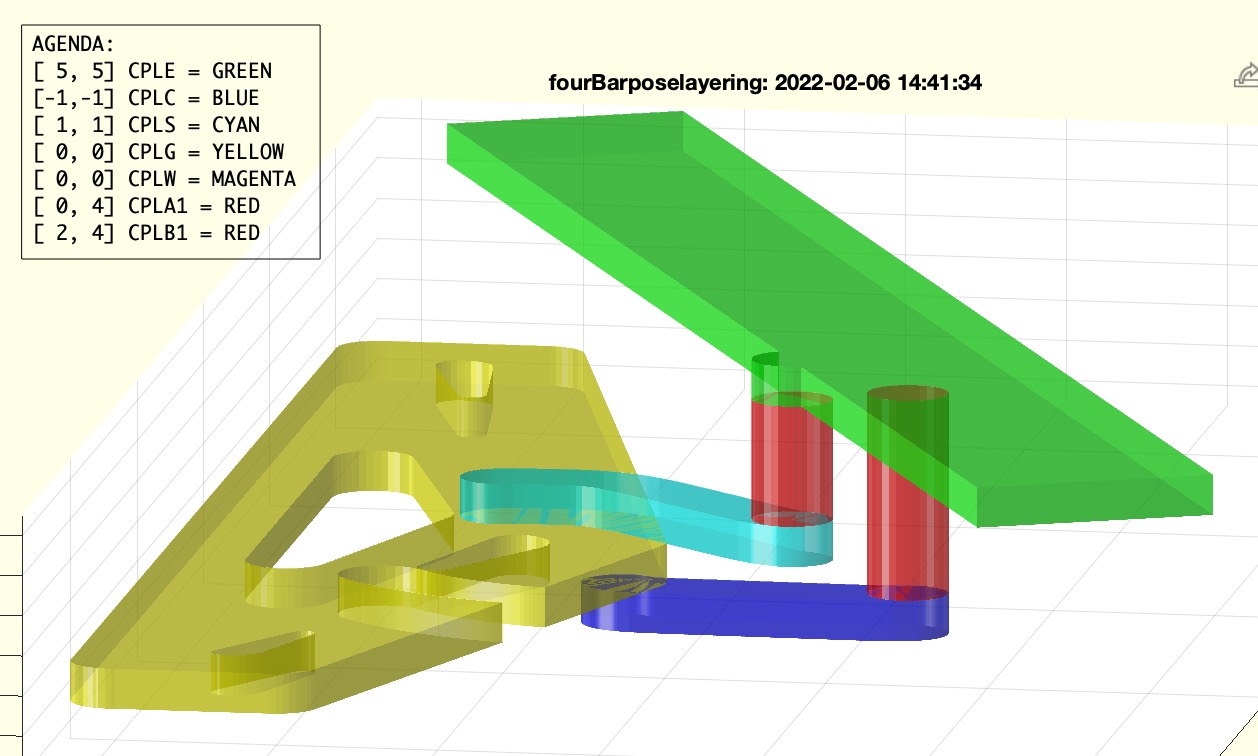 | % fourBarposelayering(PSX,aps,R12,lay,Shape,"debug","hide","wlim","full") - Creates the layering and the shaping of all 8 elements of a Fourbar linkage % (by Tim Lueth, VLFL-Lib, 2022-JAN-25 as class: KINEMATICS AND FRAMES) % % Afterwards a fnctn such as SGofCLLL to implement the assembly method. % The process: % Posesample => Posedefiniton % fourBarposesyntheses => compute fourbars with 1, 2, 3 pose synthesis % fourBarposeplotsolution => plot or animate solutions % fourBarposesortsolution => sort and select solutions % fourBarposelayering => layer and compute shape % fourBarCLLL2SGdesign => Design for assembly and 3D print % % (Status of: 2022-02-15) % % Introduced first in SolidGeometry 5.1 % % See also: CPLsubtractTLasSG, PLshortestpathinCPL, Posesample, % fourBarposesyntheses, fourBarposeplotsolution, fourBarCLLL2SGdesign % % [LLLM,TL0,TA1,TB1]=fourBarposelayering([PSX,aps,R12,lay,Shape,"debug"," % hide","wlim","full"]) % === INPUT PARAMETERS === % PSX: Pose struct include PS.solut field % aps: Single pose or selection of poses % R12: [Rout Rin Height]; default is [5 2.5 6] % lay: default is [0 2 1 1] % Shape: "A*" (default) or "Bezier" % "debug": covers the crank behind the effector % "hide": [angle-offset angle-range]; default is [0 360] % "wlim": % === OUTPUT RESULTS ====== % LLLM: Contour Link Level Layering ==> fourBarCLLL2SGdesign % TL0: % TA1: % TB1: % % EXAMPLE: % PS=PosesampleWalk % PS=fourBarposesyntheses(PS,[1 2],[15 3 3],'','','isrot,break coll CPLW CPL0'); % 200 solutions % PS=fourBarposesyntheses(PS,[1 2],[20 2.5 2.5],'','','isrot,break coll CPLW CPL0'); % 317 solutions % fourBarposeplotsolution(PS,1); % fourBarposesortsolution(PS,'crank-length',[10 inf],'coupler-length'); PSX=ans; % fourBarposelayering(PSX,1,[3 1.6 3],[0 2 1 1 -2]); CLLL=ans; % CPLW must be -2 % fourBarCLLL2SGdesign(CLLL,'',PSX.RACK) % % % See also: CPLsubtractTLasSG, PLshortestpathinCPL, Posesample, % fourBarposesyntheses, fourBarposeplotsolution, fourBarCLLL2SGdesign % % % Copyright 2022 Tim C. Lueth |
jarvismemory(PSN)- sets or gets a pose from jarvis / fourbardesignbysiri |
 | % jarvismemory(PSN) - sets or gets a pose from jarvis / fourbardesignbysiri % (by Tim Lueth, VLFL-Lib, 2022-JAN-25 as class: USER INTERFACE) % % Introduced first in SolidGeometry 5.1 % % See also: jarvis, fourbardesignbysiri % % PS=jarvismemory([PSN]) % === INPUT PARAMETERS === % PSN: New Pose to store in global variable fourbardesignbysirimem % === OUTPUT RESULTS ====== % PS: Pose stored currently in global variable fourbardesignbysirimem % % EXAMPLE: % PS=PosesampleWalk; % jarvismemory(PS); % jarvis % % See also: jarvis, fourbardesignbysiri % % % Copyright 2022 Tim C. Lueth |
SGhandle(bsiz,dins,shap)- returns a simople handle to be fixed by screws |
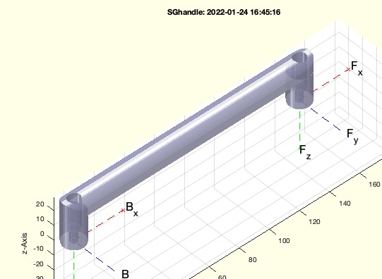 | % SGhandle(bsiz,dins,shap) - returns a simople handle to be fixed by screws % (by Tim Lueth, VLFL-Lib, 2022-JAN-24 as class: PARAMETRIC DESIGN) % % Introduced first in SolidGeometry 5.1 % % See also: SGManipulatorLink, SGdesignDIN912BushingE % % SG=SGhandle([bsiz,dins,shap]) % === INPUT PARAMETERS === % bsiz: size of handle [length radius-xy radius height height] default is % [100 14 9 20] % dins: optional screws for bushings such as [2.5 6] % shap: default is true; use false if there are boolean problems % === OUTPUT RESULTS ====== % SG: Handle geometry % % EXAMPLE: % SGhandle(150,[4 14]) % % See also: SGManipulatorLink, SGdesignDIN912BushingE % % % Copyright 2022 Tim C. Lueth |
SGcut2fit(SG,maxl,dins,ttyp)- cuts a large solid into smaller pieces to be fixed with screws |
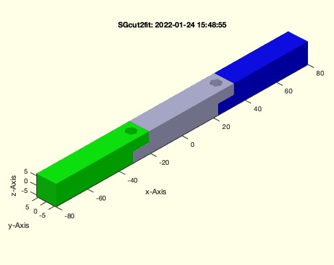 | % SGcut2fit(SG,maxl,dins,ttyp) - cuts a large solid into smaller pieces to be fixed with screws % (by Tim Lueth, VLFL-Lib, 2022-JAN-24 as class: AUTOMATIC DESIGN) % % will be renamed in SGcut2fitDIN912DIN985 % % still unstable with large surfaces and tight triangles (Status of: % 2022-01-24) % % Introduced first in SolidGeometry 5.1 % % See also: SGdesignCutDIN912DIN985 % % SGS=SGcut2fit(SG,[maxl,dins,ttyp]) % === INPUT PARAMETERS === % SG: Solid Geometry % maxl: maximal length in largest dimension % dins: screw diameter; default is [2.5 6 0] for DIN912 985 % ttyp: separation type; default is 'L' % === OUTPUT RESULTS ====== % SGS: cell list of parts % % EXAMPLE: % SGcut2fit(SGbox([160,12,12])) % % See also: SGdesignCutDIN912DIN985 % % % Copyright 2022 Tim C. Lueth |
CPLfit(CPLA,CPLB,buff,points)- fits a contour or a point list into a polygon |
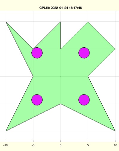 | % CPLfit(CPLA,CPLB,buff,points) - fits a contour or a point list into a polygon % (by Tim Lueth, VLFL-Lib, 2022-JAN-24 as class: CLOSED POLYGON LISTS) % % will be renamed (Status of: 2022-01-25) % % Introduced first in SolidGeometry 5.1 % % See also: CPLfitinCPL, CPLfitinCPLrot, CPLfitinCPLscale % % [CPLN,mb,f]=CPLfit(CPLA,CPLB,[buff,points]) % === INPUT PARAMETERS === % CPLA: Outside shape of a contour % CPLB: Contour to fit in or Point list for circles % buff: buffer for contour or buffer or point list % points: if true CPLB is used as point list for circles % === OUTPUT RESULTS ====== % CPLN: Contour or Point list that fits % mb: relative shift % f: scaling factor % % EXAMPLE: % CPLfit(CPLsample(3),PLsquare(1000)) % fit in % CPLfit(CPLsample(3),PLsquare(1000),1) % fit in with a border % CPLfit(CPLsample(3),PLsquare(1000),1,true) % fit in for drilling holes % % % See also: CPLfitinCPL, CPLfitinCPLrot, CPLfitinCPLscale % % % Copyright 2022 Tim C. Lueth |
strrepalias(str,word,)- replaces a set of similar words by a specified one |
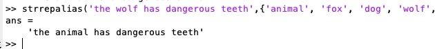 | % strrepalias(str,word,) - replaces a set of similar words by a specified one % (by Tim Lueth, VLFL-Lib, 2022-JAN-24 as class: USER INTERFACE) % % could be a thesaurus but used mainly for natural language interfaces to % correct speach or missspelling (Status of: 2022-01-29) % % Introduced first in SolidGeometry 5.1 % % See also: siri2jarvis, jarvis, fourbardesignbysiri, strrepn, strfindex, % strfindafter, strfindtag % % str=strrepalias(str,word,[]) % === INPUT PARAMETERS === % str: string % word: {'animal', 'fox', 'dog', 'wolf', 'wolfhound', 'dog', 'hound'; 2nd % line} % === OUTPUT RESULTS ====== % str: modified string % % EXAMPLE: % strrepalias('the wolf has dangerous teeth',{'animal', 'fox', 'dog', 'wolf', 'wolfhound', 'dog', 'hound'}) % % See also: siri2jarvis, jarvis, fourbardesignbysiri, strrepn, strfindex, % strfindafter, strfindtag % % % Copyright 2022 Tim C. Lueth |
SGisempty(SG)- returns wether a solid is empty / has not faces or not |
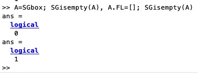 | % SGisempty(SG) - returns wether a solid is empty / has not faces or not % (by Tim Lueth, VLFL-Lib, 2022-JAN-21 as class: SURFACES) % % necessary because of the many methods to represent solidsis (Status of: % 2022-01-21) % % Introduced first in SolidGeometry 5.1 % % See also: isSG % % ie=SGisempty(SG) % === INPUT PARAMETERS === % SG: Solid geometry % === OUTPUT RESULTS ====== % ie: true if there are no surfaces % % See also: isSG % % % Copyright 2022 Tim C. Lueth |
matlabopen- open the matlab application on mac |
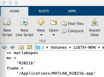 | % matlabopen - open the matlab application on mac % (by Tim Lueth, VLFL-Lib, 2022-JAN-21 as class: USER INTERFACE) % % Some more complex matlab programms such as "fourbardesignbysiri" use % different other application programms such as Filemaker or quickcams % etc. % By starting those external applications by fnctn openbydoubleclick, the % mouse focus switch to the new called application, and typed letters are % processed in a different app. This is very confusing for a user. % Therefor, the fnctn openbydoubleclick will use matlabopen to switch the % user control back to matlab if this is desired. % Currently tested only on mac osx using % - cura % - SGfilemaker % - quickcamopen (Status of: 2022-01-21) % % Introduced first in SolidGeometry 5.1 % % See also: openbydoubleclick, commandwindow, shg, editorwindow, cura % % matlabopen % % See also: openbydoubleclick, commandwindow, shg, editorwindow, cura % % % Copyright 2022 Tim C. Lueth |
SGdesignCutDIN912DIN985(SG,T,DINS,TTPP,zcut,supp,bsiz,"debug")- Creates a body cut with subsequent screwing possibility bue straigt cut or z cut |
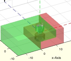 | % SGdesignCutDIN912DIN985(SG,T,DINS,TTPP,zcut,supp,bsiz) - Creates a body cut with subsequent screwing possibility bue straigt cut or z cut % (by Tim Lueth, VLFL-Lib, 2022-JAN-20 as class: AUTOMATIC DESIGN) % % See also SGcutT4design of 2020-Aug(!) which is even more advanced for % joints to create. Good example for forgetting know how within 18 month % by myself! % Nevertheless, very powerful fuction (Status of: 2022-01-21) % % Introduced first in SolidGeometry 5.1 % % See also: SGcutT4design, SGseparatebyPez, SGdesignDIN912DIN985, % SGcutTcrossblade, SGdesignSupplement, BBofSGcutT % % [SGH,SGN,T]=SGdesignCutDIN912DIN985([SG,T,DINS,TTPP,zcut,supp,bsiz]) % === INPUT PARAMETERS === % SG: Solid Geometry % T: Frame to cut % DINS: size of screws default is [2.5 6 0] % TTPP: screw type 'TT' or 'PP' % zcut: false or 'L' or 'Z' or 'M' % supp: add solids as supplement; defaut is false % bsiz: default is 0.05 % === OUTPUT RESULTS ====== % SGH: Head side (positive ez) % SGN: Nut side (positive ez) % T: Used cutting frame % % EXAMPLE: % SGdesignCutDIN912DIN985(SGbox,TofPez([10 0 0],[1 0 0])) % SGdesignCutDIN912DIN985(SGbox,TofPez([10 0 0],[0 1 0])) % A=SGtrans0(SGcylinder(10,100)); B=SGrotate(A,'y',pi/2); C=SGrotate(A,'x',pi/2); SGfigure({A,B,C}) % % % See also: SGcutT4design, SGseparatebyPez, SGdesignDIN912DIN985, % SGcutTcrossblade, SGdesignSupplement, BBofSGcutT % % % Copyright 2022 Tim C. Lueth |
Posemagnify(PS,m)- scales the size of Pose struct dimensions |
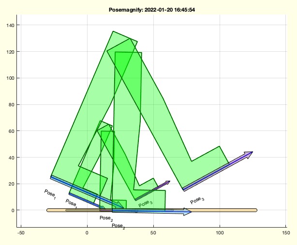 | % Posemagnify(PS,m) - scales the size of Pose struct dimensions % (by Tim Lueth, VLFL-Lib, 2022-JAN-20 as class: KINEMATICS AND FRAMES) % % Introduced first in SolidGeometry 5.1 % % See also: PosetransrelCPLE, PosetransrelGPL, Posetransui % % PS=Posemagnify(PS,m) % === INPUT PARAMETERS === % PS: Pose % m: magnification factor % === OUTPUT RESULTS ====== % PS: Magnified Pose struct % % See also: PosetransrelCPLE, PosetransrelGPL, Posetransui % % % Copyright 2022 Tim C. Lueth |
exp_2022_01_20_barcut- EXPERIMENT TO CUT AND ASSSEMBLE A SOLID WITH SCREWS |
 | % exp_2022_01_20_barcut - EXPERIMENT TO CUT AND ASSSEMBLE A SOLID WITH SCREWS % (by Tim Lueth, VLFL-Lib, 2022-JAN-20 as class: EXPERIMENTS) % % ======================================================================= % OBSOLETE (2022-01-21) - USE 'SGdesignCutDIN912DIN985' INSTEAD % ======================================================================= % % Introduced first in SolidGeometry 5.1 % % See also: [ SGdesignCutDIN912DIN985 ] ; SGcutTcrossblade, % SGdesignDIN912DIN985 % % exp_2022_01_20_barcut % % See also: [ SGdesignCutDIN912DIN985 ] ; SGcutTcrossblade, % SGdesignDIN912DIN985 % % % Copyright 2022 Tim C. Lueth |
exp_2022_01_19_Posechain(PSA,ss)- EXPERIMENT TO CREATE A RELATIVE MOVING FOURBAR LINKAGE AS FOOT FOR A WALKIN Mechanism |
 | % exp_2022_01_19_Posechain(PSA,ss) - EXPERIMENT TO CREATE A RELATIVE MOVING FOURBAR LINKAGE AS FOOT FOR A WALKIN Mechanism % (by Tim Lueth, VLFL-Lib, 2022-JAN-19 as class: EXPERIMENTS) % % Introduced first in SolidGeometry 5.1 % % PS=exp_2022_01_19_Posechain(PSA,[ss]) % === INPUT PARAMETERS === % PSA: % ss: % === OUTPUT RESULTS ====== % PS: % % EXAMPLE: % PSA=PosesampleWalk % PSA=fourBarposesyntheses(PSA,[1 2 3],30,[1 2 3],'','isrot') % exp_2022_01_19_Posechain(PSA,1) % % % Copyright 2022 Tim C. Lueth |
raamboserialconnect(portname)- resets and installs a serial communcation using for a Raambo Robot of ERGOSURG |
 | % raamboserialconnect(portname) - resets and installs a serial communcation using for a Raambo Robot of ERGOSURG % (by Tim Lueth, VLFL-Lib, 2022-JAN-18 as class: KINEMATICS AND FRAMES) % % work thanks to D. Zhang, S. Laudahn und S. Schiele (Status of: % 2022-02-02) % % Introduced first in SolidGeometry 5.1 % % See also: serialportused % % [s,text]=raamboserialconnect([portname]) % === INPUT PARAMETERS === % portname: COM# or usbmodem1431101 % === OUTPUT RESULTS ====== % s: serial port % text: recordred text during boot process % % EXAMPLE: % s=raamboterminal % % % See also: serialportused % % % Copyright 2022 Tim C. Lueth |
serialportused- returns the ports that are in use already |
 | % serialportused - returns the ports that are in use already % (by Tim Lueth, VLFL-Lib, 2022-JAN-18 as class: AUXILIARY PROCEDURES) % % Introduced first in SolidGeometry 5.1 % % See also: raamboterminal, serialportlist, serialportused % % % su=serialportused % === OUTPUT RESULTS ====== % su: serial in use % % EXAMPLE: % serialportused % % See also: raamboterminal, serialportlist, serialportused % % % % Copyright 2022 Tim C. Lueth |
jarvis(domain)- Natural Language Interface JARVIS |
 | % jarvis(domain) - Natural Language Interface JARVIS % (by Tim Lueth, VLFL-Lib, 2022-JAN-18 as class: USER INTERFACE) % % J.A.R.V.I.S: Tim's "Just Amazing Rather Very Intelligent System" and % not just another one from Tony ;-) % condition is circular =isrot % condition is limited =norot % new condition, add condition, remove condition (Status of: 2022-01-29) % % Introduced first in SolidGeometry 5.1 % % See also: fourbardesignbysiri, SGofCPLcommandui, SGtransrelSG, % CPLtransrelCPL, siri2jarvis % % jarvis([domain]) % === INPUT PARAMETERS === % domain: knowledge domains; default is '4Bars' % % EXAMPLE: % jarvis('4bars') % jarvis('robots') % % See also: fourbardesignbysiri, SGofCPLcommandui, SGtransrelSG, % CPLtransrelCPL, siri2jarvis % % % Copyright 2022 Tim C. Lueth |
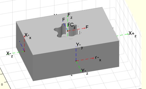
SGdesignDrivenshaft(M,L,sl,KK,"debug")- Designs a torque transmitting shaft |
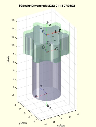 | % SGdesignDrivenshaft(M,L,sl,KK) - Designs a torque transmitting shaft % (by Tim Lueth, VLFL-Lib, 2022-JAN-17 as class: AUTOMATIC DESIGN) % % For insert either use the Frame FC or use negative overlength of the % screw if subtracting the Head as shown in exp_2022_01_17_axle % % (Status of: 2022-01-17) % % Introduced first in SolidGeometry 5.1 % % See also: SGdesignDIN912DIN985, SGdesignDIN912BushingE, % SGdesignSupplement % % [H,N,S]=SGdesignDrivenshaft([M,L,sl,KK]) % === INPUT PARAMETERS === % M: Diameter of [Cylinder Torx-Top Torx Bottom] % L: Length of [Middle Top Bottom] % sl: fitting for subtraction solids % KK: Kerbkonus [Top bottom] % === OUTPUT RESULTS ====== % H: Subtraction solid of Top Torx ('F') % N: Subtraction solid of Bottom Torx ('B') % S: Geometry of the Torque pin % % EXAMPLE: % SGdesignDrivenshaft([6 10],[10 4],'c') % [H,N,S]=SGdesignDrivenshaft([6 10],[10 4],'c') % A=SGsubtract(SGbox([31 21 11]),H,'alignT',{'C','F'}); SGwriteSTL(A,'Box'); % H=SGtransrelSG(H,A,'alignT',{'C','F'}); A=SGTset(A,'FC',SGTget(H,'F')); % % [HE,NE,SE]=SGdesignDIN912BushingE([2.5 8 0]); % SGsubtract(S,NE,'alignT',{'C','F'}); B=ans; % SGsubtract(A,HE,'alignT',{'C','FC'}); C=ans; % % % See also: SGdesignDIN912DIN985, SGdesignDIN912BushingE, % SGdesignSupplement % % % Copyright 2022 Tim C. Lueth |
exp_2022_01_17_axle (,"debug")- EXPERIMENT TO SEE HOW TO USE SGdesignDrivenshaft and getfuncparamStr |
 | % exp_2022_01_17_axle (,"debug") - EXPERIMENT TO SEE HOW TO USE SGdesignDrivenshaft and getfuncparamStr % (by Tim Lueth, VLFL-Lib, 2022-JAN-17 as class: EXPERIMENTS) % % Introduced first in SolidGeometry 5.1 % % See also: SGdesignDrivenshaft, getfuncparamStr % % exp_2022_01_17_axle([,"debug"]) % "debug": show progress if used % % See also: SGdesignDrivenshaft, getfuncparamStr % % % Copyright 2022 Tim C. Lueth |
exp_2022_01_17_Theo_Jansen- EXPERIMENT TO USE THE ORIGINAL SAND BEAST DIMENSIONS FROM THEO JANSEN OF 1991 |
 | % exp_2022_01_17_Theo_Jansen - EXPERIMENT TO USE THE ORIGINAL SAND BEAST DIMENSIONS FROM THEO JANSEN OF 1991 % (by Tim Lueth, VLFL-Lib, 2022-JAN-17 as class: EXPERIMENTS) % % See also Tschebyschow-Lambda-Mechanismus, (Status of: 2022-01-18) % % Introduced first in SolidGeometry 5.1 % % See also: https://youtu.be/FFS-2axFo1Y, % https://en.etudes.ru/etudes/tchebyshev-plantigrade-machine % % exp_2022_01_17_Theo_Jansen % % See also: https://youtu.be/FFS-2axFo1Y, % https://en.etudes.ru/etudes/tchebyshev-plantigrade-machine % % % Copyright 2022 Tim C. Lueth |
SGdemoulding(SG,an,ct,hl)- Creates demolding chamfers for cast objects |
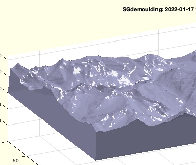 | % SGdemoulding(SG,an,ct,hl) - Creates demolding chamfers for cast objects % (by Tim Lueth, VLFL-Lib, 2022-JAN-17 as class: SURFACES) % % written for Wolfram Volk % % CPLofSGcutT(SG,TofP([0 0 40])) (Status of: 2022-01-17) % % Introduced first in SolidGeometry 5.1 % % See also: CPLofSGcutT % % SG=SGdemoulding(SG,[an,ct,hl]) % === INPUT PARAMETERS === % SG: Solif Geometry % an: angle for demolding chamfers % ct: bordercut; default is -0.1 % hl: % === OUTPUT RESULTS ====== % SG: % % EXAMPLE: % SG=SGreadSTL('/Users/timlueth/Downloads/STL Grindewald/Grindelwald.STL'); % SGdemoulding(SG,2); SGM=ans; % SGwriteSTL(SGM,'GrindelwaldM2') % % See also: CPLofSGcutT % % % Copyright 2022 Tim C. Lueth |
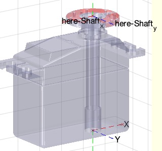
exp_2022_01_16_servosample(SG,FN,sbb)- EXPERIMENT TO EXPLAIN HOW TO ADD AUTOMATICALLY BEARING AND AN AXLE TO A SOLID |
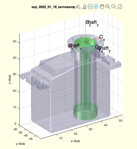 | % exp_2022_01_16_servosample(SG,FN,sbb) - EXPERIMENT TO EXPLAIN HOW TO ADD AUTOMATICALLY BEARING AND AN AXLE TO A SOLID % (by Tim Lueth, VLFL-Lib, 2022-JAN-16 as class: EXPERIMENTS) % % The fnctns, SGdesignAxlebearing, SGdesignSupplement, SGunion are used % to create the solid before a second time SGdesignAxlebearing is used to % create the final solid for the bearing % SGservosample(3) is a watertight sample. % (Status of: 2022-01-16) % % Introduced first in SolidGeometry 5.1 % % See also: SGservosample, SGdesignAxlebearing, SGdesignSupplement, % SGunion % % SGN=exp_2022_01_16_servosample([SG,FN,sbb]) % === INPUT PARAMETERS === % SG: Solid Geometry % FN: Frame Name % sbb: BEaring size; default [6 13 5 0] % === OUTPUT RESULTS ====== % SGN: % % EXAMPLE: % exp_2022_01_16_servosample(SGservosample(3),'Shaft',[6 13 5]); % % See also: SGservosample, SGdesignAxlebearing, SGdesignSupplement, % SGunion % % % Copyright 2022 Tim C. Lueth |
PLshaftrad(r,d,b)- creates a PL for a contour for SGofCPLrot |
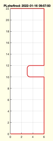 | % PLshaftrad(r,d,b) - creates a PL for a contour for SGofCPLrot % (by Tim Lueth, VLFL-Lib, 2022-JAN-16 as class: CLOSED POLYGON LISTS) % % easier to understand fnctn to create axles % for second parameter b see 3rd parameter of PLradialEdges (Status of: % 2022-01-16) % % Introduced first in SolidGeometry 5.1 % % See also: CPLmotorshaft, PLradialEdges % % PL=PLshaftrad([r,d,b]) % === INPUT PARAMETERS === % r: [r1 r2 r3 ....] radius % d: distances between steps % b: [radius breakrule] breaking the edges; default is [0.5 -1] % === OUTPUT RESULTS ====== % PL: Point list of a shaft % % EXAMPLE: % PLshaftrad([1 2 1],[0 2 2],'',true); PL=ans; % RAMP % PLshaftrad([6 3 6],[10 2 10],[.5 -1]); PL=ans; % only concave % PLshaftrad([6 3 6],[10 2 10],[.5 +1]); PL=ans; % only convex % PLshaftrad([6 3 6],[10 2 10],[.5 0 ]); PL=ans; % both edges % PLshaftrad([6 3 6],[10 2 10],[0 0 ]); PL=ans; % no radial edges % PLshaftrad([6 3 6],[10 2 10],[.5 0]); PL=ans; pause(1); SGofCPLrot(PL) % create the solid % % See also: CPLmotorshaft, PLradialEdges % % % Copyright 2022 Tim C. Lueth |
getfuncparamStr(n,args,v,fillin,"debug","A0")- similar as getfuncparams but works with strings prpoerties |
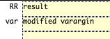 | % getfuncparamStr(n,args,v,fillin) - similar as getfuncparams but works with strings prpoerties % (by Tim Lueth, VLFL-Lib, 2022-JAN-15 as class: AUXILIARY PROCEDURES) % % Not part of the documentation tool yet, but works as programming method % (Status of: 2022-01-17) % % Introduced first in SolidGeometry 5.1 % % See also: getfuncparams % % [RR,var]=getfuncparamStr(n,args,v,[fillin]) % === INPUT PARAMETERS === % n: number or string of argument % args: arguments such as varargins % v: default value or empty, if simple bollean % fillin: % === OUTPUT RESULTS ====== % RR: result % var: modified varargin % % EXAMPLE: % [isdebug,varargin]=getfuncparamStr('debug',varargin,''); % True if the string "debug" is parameter % [A0,varargin]=getfuncparamStr('A0',varargin,[0 0]); % Finds "A0" with subsequent coordinates % % % See also: getfuncparams % % % Copyright 2022 Tim C. Lueth |
SGTretain(SG,FN2R)- removes frames but retains some |
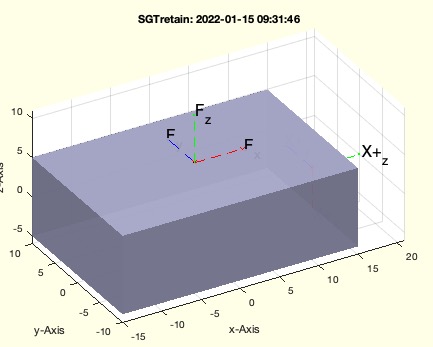 | % SGTretain(SG,FN2R) - removes frames but retains some % (by Tim Lueth, VLFL-Lib, 2022-JAN-15 as class: KINEMATICS AND FRAMES) % % Introduced first in SolidGeometry 5.1 % % See also: SGTget, SGTset, SGTplot, SGTremove, SGTui, SGTframeplot, % SGTrename, SGTsetofFS % % SG=SGTretain(SG,[FN2R]) % === INPUT PARAMETERS === % SG: Solid Geomnetry struct with fields 'Tname', 'T', 'FTiL' % FN2R: % === OUTPUT RESULTS ====== % SG: Struct with removed frames % % EXAMPLE: % SGTretain(SGbox,'F','X+') % SGTrename(ans,'X+','B') % % See also: SGTget, SGTset, SGTplot, SGTremove, SGTui, SGTframeplot, % SGTrename, SGTsetofFS % % % Copyright 2022 Tim C. Lueth |
BUYballbearing(Ri)- returns a list of buyable and used standard parts for ball bearings |
 | % BUYballbearing(Ri) - returns a list of buyable and used standard parts for ball bearings % (by Tim Lueth, VLFL-Lib, 2022-JAN-14 as class: USER INTERFACE) % % Introduced first in SolidGeometry 5.1 % % See also: SGdesignDIN912DIN985axialbearing, % SGdesignDIN912DIN985axradbearing % % TL=BUYballbearing([Ri]) % === INPUT PARAMETERS === % Ri: Inner Diameter % === OUTPUT RESULTS ====== % TL: Table list % % See also: SGdesignDIN912DIN985axialbearing, % SGdesignDIN912DIN985axradbearing % % % Copyright 2022 Tim C. Lueth |
CPLcutPez(CPL,cp,ev)- cuts a CPL along a border line |
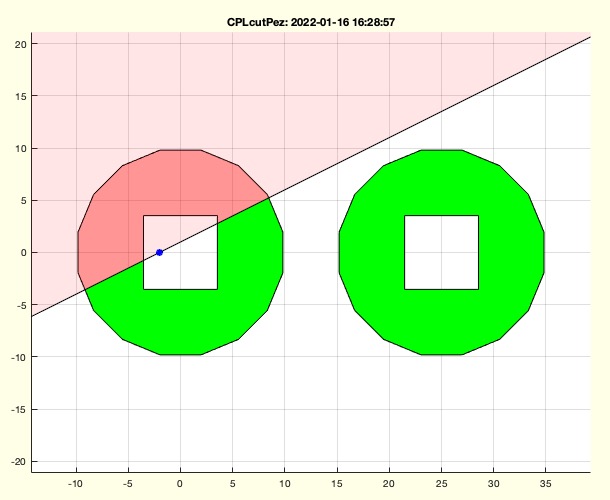 | % CPLcutPez(CPL,cp,ev) - cuts a CPL along a border line % (by Tim Lueth, VLFL-Lib, 2022-JAN-14 as class: CLOSED POLYGON LISTS) % % Introduced first in SolidGeometry 5.1 % % See also: CPLsubtract % % CPR=CPLcutPez(CPL,[cp,ev]) % === INPUT PARAMETERS === % CPL: Closed Polygon List % cp: center Point % ev: unit vector to erase from % === OUTPUT RESULTS ====== % CPR: cutted contour % % EXAMPLE: % CPLcutPez(PLcircle(10),[-2 0],[-1 2]); % CPLcutPez(CPLsample(12),[-2 0],[-1 2]); % % See also: CPLsubtract % % % Copyright 2022 Tim C. Lueth |
SGdesignAxlebearing(SG,FN,sbb,sch)- cretaes the material subtraction from a solid for radial bearings and axle |
 | % SGdesignAxlebearing(SG,FN,sbb,sch) - cretaes the material subtraction from a solid for radial bearings and axle % (by Tim Lueth, VLFL-Lib, 2022-JAN-13 as class: AUTOMATIC DESIGN) % % This fnctn differs a little from the other deisng fnctn, since it has % to detect automatically wethere there is a need for two or just one % bearings % Automatic Design, since it measures the axle depth and automatically % decides to use one or two bearings (Status of: 2022-01-15) % % Introduced first in SolidGeometry 5.1 % % See also: SGdesignBallbearing, SGdesignDIN912BushingE, % SGdesignDIN912DIN985axialbearing % % [SG,SS,S,dd]=SGdesignAxlebearing([SG,FN,sbb,sch]) % === INPUT PARAMETERS === % SG: Solid geometry that needs a bearingx % FN: Framename or T or {'FN1', 'FN2'} % sbb: [Ri Ro depth os], default is [2.5 6 1.8] % sch: % === OUTPUT RESULTS ====== % SG: Modified Solid % SS: Length of Axle % S: % dd: % % EXAMPLE: % SGdesignAxlebearing('','F',[2.5 6 3.4 5]) % SGdesignAxlebearing('','F',[2.5 6 3.4]) % SGdesignAxlebearing(SGservosample(3),'Shaft',[2.5 6 3.4 5]) % % See also: SGdesignBallbearing, SGdesignDIN912BushingE, % SGdesignDIN912DIN985axialbearing % % % Copyright 2022 Tim C. Lueth |
CPLofspokedPL(PL,wt,rd)- converts a point list into a spokes between the most distance points |
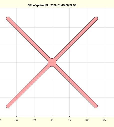 | % CPLofspokedPL(PL,wt,rd) - converts a point list into a spokes between the most distance points % (by Tim Lueth, VLFL-Lib, 2022-JAN-13 as class: CLOSED POLYGON LISTS) % % Introduced first in SolidGeometry 5.1 % % See also: CPLrack4PL, CPLrackPLdelaunay, SGwheelspoked % % CPL=CPLofspokedPL([PL,wt,rd]) % === INPUT PARAMETERS === % PL: Point list % wt: Radius = half spoke thickness % rd: Radius to avoid notch effect inside; default is 0.5 % === OUTPUT RESULTS ====== % CPL: % % EXAMPLE: % CPLofspokedPL(60*rand(10,2),1); % standard graffitty of the 2010th years % CPLtextimage('TL');PL=ans; pause(1); CPLofspokedPL(woNaN(PL),.1); % CPLtextimage('T');PL=ans; pause(1); CPLofspokedPL(woNaN(PL),.1); % CPLofspokedPL(PLsquare(50,50),1,2); % CPLofspokedPL(PLcircle(50,10),1,2); % CPLofspokedPL(PLcircle(50,20),1,2); % CPLofspokedPL(PLcircle(50,10),1); % CPLofspokedPL(PLcircle(50,20),1); % % See also: CPLrack4PL, CPLrackPLdelaunay, SGwheelspoked % % % Copyright 2022 Tim C. Lueth |
ELofFLpatch(FL)- converts a patch (more than triangles) list into an edge list |
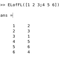 | % ELofFLpatch(FL) - converts a patch (more than triangles) list into an edge list % (by Tim Lueth, VLFL-Lib, 2022-JAN-13 as class: AUXILIARY PROCEDURES) % % returns the edge list in patch order. A more general solution than % ELofFL of July 2012 (Status of: 2022-01-13) % % Introduced first in SolidGeometry 5.1 % % See also: ELofFLborder, ELofFL, ELunique % % EL=ELofFLpatch(FL) % === INPUT PARAMETERS === % FL: Facet list (n x m) % m>=3 % === OUTPUT RESULTS ====== % EL: Edge list (n x 2) % % EXAMPLE: % FL=[1 2 3 4 5;5 4 3 2 1]; ELofFLpatch(FL), ELunique(ans) % % See also: ELofFLborder, ELofFL, ELunique % % % Copyright 2022 Tim C. Lueth |
SGwheelspoked(R,H,n,A)- returns a solid of a spoked wheel |
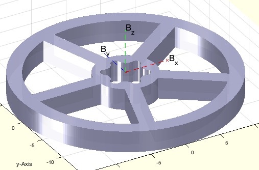 | % SGwheelspoked(R,H,n,A) - returns a solid of a spoked wheel % (by Tim Lueth, VLFL-Lib, 2022-JAN-13 as class: PARAMETRIC DESIGN) % % will be improved by using a kerbkonus and a DIN 912 etc. (Status of: % 2022-01-15) % % Introduced first in SolidGeometry 5.1 % % See also: CPLofspokedPL, SGcylinder % % [SG,CPL]=SGwheelspoked([R,H,n,A]) % === INPUT PARAMETERS === % R: [Ro Ro2 Ri]; default 15 % H: Heightand width of the spokes; default is [5 2] % n: number of spokes % A: 'T30' if there is a need for a torx axle; default is [] % === OUTPUT RESULTS ====== % SG: Solid Geometry % CPL: CPL that was extruded % % EXAMPLE: % SGwheelspoked(15,[3 2],5) % SGwheelspoked(15,[3 2],10) % SGwheelspoked(15,[3 2],5,'T30') % % See also: CPLofspokedPL, SGcylinder % % % Copyright 2022 Tim C. Lueth |
DINtorx(Mot)- returns the main paraemter for designing a metric torque adapter |
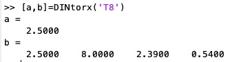 | % DINtorx(Mot) - returns the main paraemter for designing a metric torque adapter % (by Tim Lueth, VLFL-Lib, 2022-JAN-12 as class: PARAMETRIC DESIGN) % % https://de.wikipedia.org/wiki/Torx % the tightening torque could be replaced by TL(4)=DINthreadtorque(TL(1)); % The original value shows the maximum torque to be transmitted. A V2A % screw will break much earlier. (Status of: 2022-01-13) % % Introduced first in SolidGeometry 5.1 % % See also: SGsbpin, SGscrewDIN, PLhexalobular, DIN10664, % DINthreadtorque, SGtorxDIN, DINfindinTab % % [M,TL]=DINtorx([Mot]) % === INPUT PARAMETERS === % Mot: metric, or 'M2.5' or 'T30' % === OUTPUT RESULTS ====== % M: metric value % TL: [Metric, Torx, PLhexalobular-Diameter, tightening torque] % % EXAMPLE: % [a,b]=DINtorx('T8') % % See also: SGsbpin, SGscrewDIN, PLhexalobular, DIN10664, % DINthreadtorque, SGtorxDIN, DINfindinTab % % % Copyright 2022 Tim C. Lueth |
SGrackbars(L,MM,d,LY)- creates solid bars to assemble a rack for mechanisms |
 | % SGrackbars(L,MM,d,LY) - creates solid bars to assemble a rack for mechanisms % (by Tim Lueth, VLFL-Lib, 2022-JAN-12 as class: PARAMETRIC DESIGN) % % Name will change to SGrackbars (Status of: 2022-01-13) % % Introduced first in SolidGeometry 5.1 % % See also: SGdesignDIN912DIN985, SGdesignDIN912BushingE, % SGfourbarlinkageA0B0DIN912985, exp_2021_12_27_walk, SGiqlink, SGsblink % % SGrackbars([L,MM,d,LY]) % === INPUT PARAMETERS === % L: % MM: % d: % LY: % % EXAMPLE: % exp_2021_12_27_walk('','985') % % See also: SGdesignDIN912DIN985, SGdesignDIN912BushingE, % SGfourbarlinkageA0B0DIN912985, exp_2021_12_27_walk, SGiqlink, SGsblink % % % Copyright 2022 Tim C. Lueth |
fontsize4rowsfullHD(rows)- font size for lectures and video recording on 25 lines |
 | % fontsize4rowsfullHD(rows) - font size for lectures and video recording on 25 lines % (by Tim Lueth, VLFL-Lib, 2022-JAN-11 as class: VISUALIZATION) % % similar to clcl % s=settings; s.matlab.fonts.codefont.Size.PersonalValue=fs; % (Status of: 2022-01-11) % % Introduced first in SolidGeometry 5.1 % % See also: clcl % % fs=fontsize4rowsfullHD([rows]) % === INPUT PARAMETERS === % rows: 25 or 40 rows; default is 25 % === OUTPUT RESULTS ====== % fs: fontsize % % EXAMPLE: % fontsize4rowsfullHD(25) % fontsize4rowsfullHD(40) % % See also: clcl % % % Copyright 2022 Tim C. Lueth |
SGdesignDIN912BushingE(sdl,ins,tpl,W)- creates subtraction solids for a screw fixation at a specific frame position of a solid |
 | % SGdesignDIN912BushingE(sdl,ins,tpl,W) - creates subtraction solids for a screw fixation at a specific frame position of a solid % (by Tim Lueth, VLFL-Lib, 2022-JAN-10 as class: AUTOMATIC DESIGN) % % This fnctn is designed for KERBKONUS bushings % THIS FNCTN USES FITTINGS by fnctn slfit und DIN4AMfitting % If two elements should be connected using a DIN912 Screw and a % Kerbkonus bushing, this fnctn helps to create the subtraction solids to % achive a fnctnal connection using standard machine elements. % Pocket holes modified for clearancefit in height (2022-01-09) % Support spacer such as radial bearings, axial bearings (2022-01-015) % (Status of: 2022-03-10) % % Introduced first in SolidGeometry 5.1 % % See also: SGDIN912, SGDIN985, SGdesignDIN912DIN985, % SGdesignBallbearing, SGdesignSupplement, SGDINbushingE, DIN_S_BANCLOK_E % % [H,N,S,mt,parts]=SGdesignDIN912BushingE([sdl,ins,tpl,W]) % === INPUT PARAMETERS === % sdl: [M-Screw Length overlength and spacer]; default [2.5 6 0 0] % ins: Characters for "T"unnel or "P"ocket; default is 'TT' for [HEAD NUT] % tpl: Length of Insertion T/P for [HEAD NUT]; default is 10 10 % W: Rotation angle for Pocket if required; default is 0; % === OUTPUT RESULTS ====== % H: Subtraction Solid for Head side including frame 'C' % N: Subtraction Solid for Bushing side including frame 'C' % S: Srew and Nut for Visualziation including frame 'C' % mt: remaining wall thickness % parts: parts list for assembly of one connection % % EXAMPLE: % clc; [H,N,S]=SGdesignDIN912BushingE([5 10 0],'TT',40); % SGsubtract(SGbox,H,'alignT',{'C','Y-'}) % SGsubtract(SGbox,N,'alignT',{'C','Y-'}) % clc; [H,N,S]=SGdesignDIN912BushingE([2.5 6 0],'PT',40,pi/2); % SGsubtract(SGbox,H,'alignT',{'C','Y-'}); X=ans; % SGTplot(SGtransrelSG(S,X,'alignT',{'C','Y-'})) % clc; [H,N,S]=SGdesignDIN912BushingE([2.5 10 0 4],'PT',40,pi/2); % SGsubtract(SGbox,H,'alignT',{'C','Y-'}); X=ans; % SGTplot(SGtransrelSG(S,X,'alignT',{'C','Y-'})) % plot without spacer % SGTplot(SGtransrelSG(S,X,'alignT',{'C','Y-'},'transy',-4)) % plot with spacer % % % See also: SGDIN912, SGDIN985, SGdesignDIN912DIN985, % SGdesignBallbearing, SGdesignSupplement, SGDINbushingE, DIN_S_BANCLOK_E % % % Copyright 2022 Tim C. Lueth |
siri2posecommand(str)- word correction for siri misspelling and syntax check for natural language pose comands by siri |
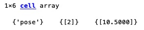 | % siri2posecommand(str) - word correction for siri misspelling and syntax check for natural language pose comands by siri % (by Tim Lueth, VLFL-Lib, 2022-JAN-10 as class: USER INTERFACE) % % ======================================================================= % OBSOLETE (2022-01-29) - USE 'siri2jarvis' INSTEAD % ======================================================================= % % may be J.A.R.V.I.S. would be better name % audiorecorderTLautostop('',44100,0.05,'',1.5); % development stopped: USE dictionarty based fnctn siri2jarvis (Status % of: 2022-01-29) % % Introduced first in SolidGeometry 5.1 % % See also: [ siri2jarvis ] ; siri2jarvis, fourbardesignbysiri, jarvis, % strrepalias, strrepn % % cmd=siri2posecommand(str) % === INPUT PARAMETERS === % str: string delivered by siri % === OUTPUT RESULTS ====== % cmd: command line for fourbardesignbysiri % % EXAMPLE: % siri2posecommand('who is number 1:10.9, 12.6 and 12.4, 6.5') % siri2posecommand('Pose number 2:10.5, 6.9 and 6.9, 12.6') % % See also: [ siri2jarvis ] ; siri2jarvis, fourbardesignbysiri, jarvis, % strrepalias, strrepn % % % Copyright 2022 Tim C. Lueth |
fourbardesignbysiri(txt,PS)- generates 4bar-linkages from a dictation fnct of Siri on MAC |
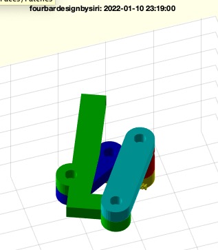 | % fourbardesignbysiri(txt,PS) - generates 4bar-linkages from a dictation fnct of Siri on MAC % (by Tim Lueth & Franz Irlinger, VLFL-Lib, 2022-JAN-10 as class: USER % INTERFACE) % % More or less a funny idea, then a fun project that then it became % serious % VERY FIRST VERSION of J.A.R.V.I.S. % An example: 1. Switch on dictate fuction on mac, call % fourbardesignbysiri and give spoken commands: % new project: % Pose 1: 0, 0 and 2,0 % Pose 2: 0,2 and 2, 2 % Pose 3: -2,0 and -2,2 % Select pose 1 and 2 and 3 % find fourbar with 10 grid points % There are actually two tasks:1) Definition of a natural language for % the textual formulation of the design tasks as a string2) Speech input % of the textual formulationThe problem arises from the fact that the % dictation fnctn is made for everyday prose, but not for technical % languages AND that Apple/Dictate, when repeating sentences, assumes % that the last formulation was probably wrong and then changes the word % choice. It therefore makes sense to first find a solution for 1 and % then one for 2, possibly having to change 1 again. (Status of: % 2022-01-15) % % Introduced first in SolidGeometry 5.1 % % See also: siri2jarvis, quickcamopen, cura, matlabopen, jarvis % % PS=fourbardesignbysiri([txt,PS]) % === INPUT PARAMETERS === % txt: string lines to interprete or empty as interpreter % PS: Pose strcut that should be modified % === OUTPUT RESULTS ====== % PS: Pose specified by language or text string % % EXAMPLE: % PS=PosesampleWalk; fourbardesignbysiri('',PS); % % See also: siri2jarvis, quickcamopen, cura, matlabopen, jarvis % % % Copyright 2022 Tim C. Lueth |
SGtorxDIN(D,L,KK,sl)- returns a TORX Pin with an optional opening for a kerbkonus bushing |
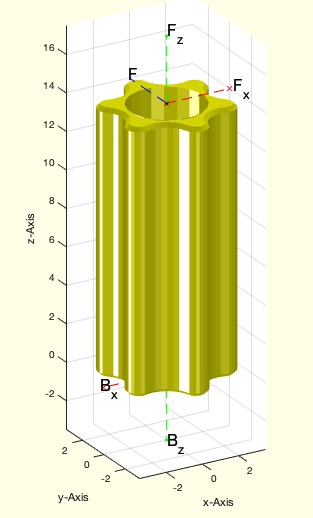 | % SGtorxDIN(D,L,KK,sl) - returns a TORX Pin with an optional opening for a kerbkonus bushing % (by Tim Lueth, VLFL-Lib, 2022-JAN-10 as class: PARAMETRIC DESIGN) % % This torx pin can be used at the end of an axle. The Torque (at % Wikipedia) is much higer than the tightening torque of V2A screws: % https://de.wikipedia.org/wiki/Torx % M T D Nm % 2.0 6 1.75 0.75 % 2.5 8 2.39 2.2 % 3.0 10 2.82 3.7 % 4.0 20 3.94 10 % 5.0 25 4.52 16 % 6.0 30 5.61 31 % 8.0 45 7.95 86 % 10 50 8.94 132 (Status of: 2022-01-15) % % Introduced first in SolidGeometry 5.1 % % See also: SGsbpin, SGscrewDIN, PLhexalobular, DIN10664, % DINthreadtorque, DINtorx % % [SG,SGX,TL]=SGtorxDIN([D,L,KK,sl]) % === INPUT PARAMETERS === % D: Diameter or string 'T30' etc. % L: length and edge; default is [14 0.3] % KK: kerbkonus metrix [top bottom] default is [0 0]; could be autom. too % sl: fitting only for SGX; default is 'c' % === OUTPUT RESULTS ====== % SG: Solid Geometry % SGX: Subtraction solid % TL: selected table of DINtorx % % EXAMPLE: % SGtorxDIN ('M5',14) % SGtorxDIN ('T30',14) % A=SGsbpin([10 .2],6); B=SGtorxDIN(6,[4 .2]); C=SGtransrelSG(B,A,'ontop',-0.2,'cat') % % See also: SGsbpin, SGscrewDIN, PLhexalobular, DIN10664, % DINthreadtorque, DINtorx % % % Copyright 2022 Tim C. Lueth |
SGDINbushingE(M)- creates a solid for a kerb konus busing |
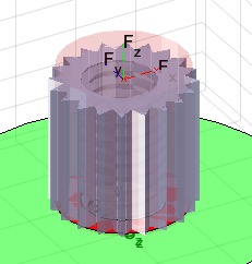 | % SGDINbushingE(M) - creates a solid for a kerb konus busing % (by Tim Lueth, VLFL-Lib, 2022-JAN-09 as class: PARAMETRIC DESIGN) % % Introduced first in SolidGeometry 5.1 % % See also: DIN_S_BANCLOK_E, SGDIN912 % % [SG,TL,SGX]=SGDINbushingE([M]) % === INPUT PARAMETERS === % M: metric 2.0, 2.5, 3, 4, 5, 6 % === OUTPUT RESULTS ====== % SG: Solid Geometry % TL: Table from DIN_S_BANCLOK_E % % SGX: Subtraction solid for intereference fit (hammer or press) % % EXAMPLE: % SGDINbushingE(2.5) % % See also: DIN_S_BANCLOK_E, SGDIN912 % % % Copyright 2022 Tim C. Lueth |
exp_2022_01_09_kerbonus- Experiment to validate dimensions of kerb konus inserts |
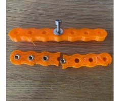 | % exp_2022_01_09_kerbonus - Experiment to validate dimensions of kerb konus inserts % (by Tim Lueth, VLFL-Lib, 2022-JAN-09 as class: EXPERIMENTS) % % Experiment to validate the bore diameters with the notch cone thread % insert M2.5. At 3.9 mm, the 3D printed plastic body was cracked when % hammered in (pressing in might have worked). It held at 4.0, 4.1 and % 4.2. Standard values are 4.0 (3.9+0.1), i.e. standard dimensions for % drill bits.An interference fit was used: % If the tightening torque is too high, the threaded bushing will be % pulled out of the plastic part. (Status of: 2022-01-09) % % Introduced first in SolidGeometry 5.1 % % See also: DIN_S_BANCLOK_E, slfit % % exp_2022_01_09_kerbonus % % EXAMPLE: exp_2022_01_09_kerbonus % % % See also: DIN_S_BANCLOK_E, slfit % % % Copyright 2022 Tim C. Lueth |
DIN_S_BANCLOK_E(M)- returns the Dimensions of the Kerbkonus Product S-BANCLOK-E |
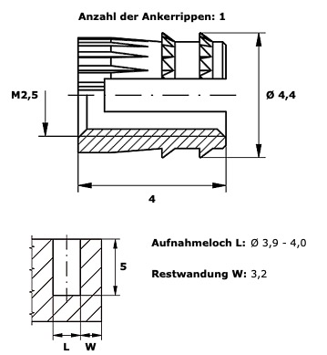 | % DIN_S_BANCLOK_E(M) - returns the Dimensions of the Kerbkonus Product S-BANCLOK-E % (by Tim Lueth, VLFL-Lib, 2022-JAN-09 as class: MECHANICAL PROCEDURES) % % The table S-BANCLOK-E has the following columns. All values are given % in millimeter % 'M','OuterDiameter','Length','HoleDiameter','ProductNumber' % The kerbkonus hole requires a interference fit slfit('i') qdded to the % radius (Tab(4)/2) % Order at C.Freitag@kerbkonus.de % https://www.kerbkonus.de/proddb/pdf/de.ds.30.pdf % (Status of: 2022-01-09) % % Introduced first in SolidGeometry 5.1 % % See also: DIN13, DIN20273, DIN336, DIN433, DIN464, DIN4AMfitting, % DIN7991, DIN912, DIN913, DIN934, DIN965, DIN985, DINfindinTab, DINhelp, % DINthreadtorque % % [M,TL]=DIN_S_BANCLOK_E(M) % === INPUT PARAMETERS === % M: metric treat diameter % === OUTPUT RESULTS ====== % M: M that was used for the table entry % TL: Table entry for M % % EXAMPLE: % DIN_S_BANCLOK_E % [M,TL]=DIN_S_BANCLOK_E(2.5); TL(1:4) % DINthreadtorque(2.5) % Tightening torque for the screw % PLcircle(TL(4)/2+slfit('i')) % dimensions of the hole % web('www.kerbkonus.de') % % See also: DIN13, DIN20273, DIN336, DIN433, DIN464, DIN4AMfitting, % DIN7991, DIN912, DIN913, DIN934, DIN965, DIN985, DINfindinTab, DINhelp, % DINthreadtorque % % % Copyright 2022 Tim C. Lueth |
CPLrackPLdelaunay(PL,b)- returns a minimal CPL bar structure that contains all points of PL |
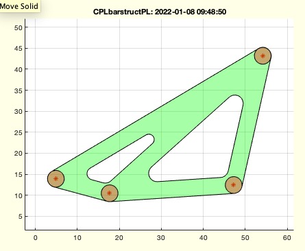 | % CPLrackPLdelaunay(PL,b) - returns a minimal CPL bar structure that contains all points of PL % (by Tim Lueth, VLFL-Lib, 2022-JAN-08 as class: CLOSED POLYGON LISTS) % % used to define rack strctures % Uses delaunay and not VLnearestNeighborN to avoid small angles (Status % of: 2022-01-08) % % Introduced first in SolidGeometry 5.1 % % See also: CPLextendbyPL, CPLrack4PL % % CPL=CPLrackPLdelaunay([PL,b]) % === INPUT PARAMETERS === % PL: Point list % b: buffer size around PL % === OUTPUT RESULTS ====== % CPL: final contour % % EXAMPLE: % PL=60*rand(4,2); CPLrackPLdelaunay(PL,2); % just repeat the call % % See also: CPLextendbyPL, CPLrack4PL % % % Copyright 2022 Tim C. Lueth |
VLnearestNeighborN(VL1,VL2,N,D)- returns the N nearest Neighbors between two point lists |
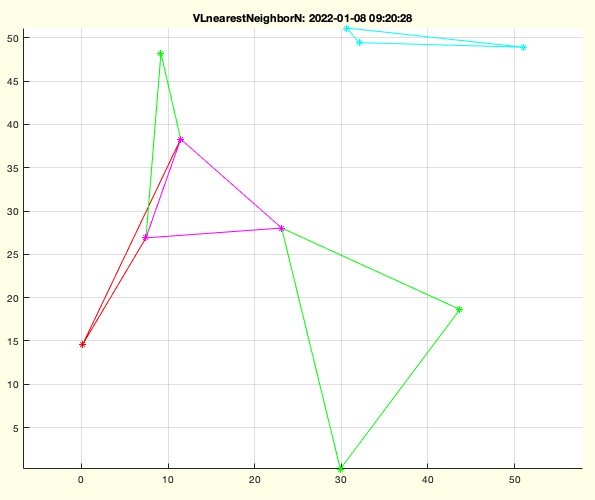 | % VLnearestNeighborN(VL1,VL2,N,D) - returns the N nearest Neighbors between two point lists % (by Tim Lueth, VLFL-Lib, 2022-JAN-08 as class: ANALYTICAL GEOMETRY) % % Slower than VLnearestNeighbor beacuse of combinatorial complexity % If you just need triangles, rethink about delaunay triangulation % (Status of: 2022-01-13) % % Introduced first in SolidGeometry 5.1 % % See also: VLnearestNeighbor, nearestpair, nearestcluster, PLcorrelate, % VLcorrelate % % [nn,nd]=VLnearestNeighborN(VL1,VL2,[N,D]) % === INPUT PARAMETERS === % VL1: Point list 1 % VL2: Point list 2 % N: selection of neighbors; default is [2:3] % D: ''ascend' (default) or 'descend' % === OUTPUT RESULTS ====== % nn: rows of neigbors for VL1 in List VL2 % nd: distance to neighbors from VL1 to VL2 % % EXAMPLE: % PL=60*rand(10,2); VLnearestNeighborN(PL,PL,2:3); % creates Triangles % PL=60*rand(10,2); VLnearestNeighborN(PL,PL,2:4); % creates Squares % PL=60*rand(10,2); VLnearestNeighborN(PL,PL,1:size(PL,1)) % creates full mesh % PL=PLcircle(50,10); VLnearestNeighborN(PL,PL,[1],'descend') % Spokes % PL=PLcircle(50,10); VLnearestNeighborN(PL,PL,[2 3],'descend') % Spokes % PL=PLcircle(50,10); VLnearestNeighborN(PL,PL,[2 3],'descend'); FL=[[1:size(PL,1)]' ans] % % See also: VLnearestNeighbor, nearestpair, nearestcluster, PLcorrelate, % VLcorrelate % % % Copyright 2022 Tim C. Lueth |
CPLcrossCPLpathlimit(CPLW,CPLE,TL0,WW,lim)- collision detection along a path in 2D |
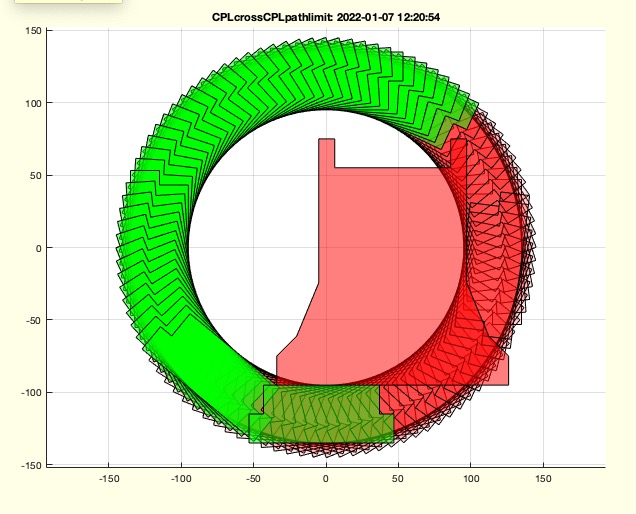 | % CPLcrossCPLpathlimit(CPLW,CPLE,TL0,WW,lim) - collision detection along a path in 2D % (by Tim Lueth, VLFL-Lib, 2022-JAN-07 as class: KINEMATICS AND FRAMES) % % Introduced first in SolidGeometry 5.1 % % See also: fourbarcollABGPL % % [wint,AA,aint,cutw]=CPLcrossCPLpathlimit(CPLW,CPLE,TL0,[WW,lim]) % === INPUT PARAMETERS === % CPLW: Static Object % CPLE: Moving Object % TL0: List of Frames to move % WW: List of corresponding values of % lim: allowed area collision; default is 0 % === OUTPUT RESULTS ====== % wint: angle intervals with respect to WW % AA: maximum intersection per interval % aint: % cutw: cutting condition % % EXAMPLE: % PS=Posesample('Tiegel'); % PS.CPLM=PLtrans1(PLsquare(50,150))+[100 0]; fourBarposesyntheses(PS,[1 2],[10 5 5]); PSN=ans; % [~,TL0,~,~,~,~,WW]=PLofFourbarcouplercurve(PSN,1); % CPLcrossCPLpathlimit (PSN.CPLW,PSN.CPLE,TL0,WW,0.01) % CPLcrossCPLpathlimit (PSN.CPLW,PSN.CPLE,TLofPL(PLcircle(100,100)),'',0.00) % % % See also: fourbarcollABGPL % % % Copyright 2022 Tim C. Lueth |
exp_2022_01_06_fourBarposesyntheses- EXPERIMENT TO SHOW THE USE OF THE FNCT fourBarposesyntheses |
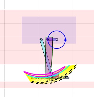 | % exp_2022_01_06_fourBarposesyntheses - EXPERIMENT TO SHOW THE USE OF THE FNCT fourBarposesyntheses % (by Tim Lueth, VLFL-Lib, 2022-JAN-06 as class: EXPERIMENTS) % % Introduced first in SolidGeometry 5.1 % % See also: fourBarposesyntheses % % exp_2022_01_06_fourBarposesyntheses % % See also: fourBarposesyntheses % % % Copyright 2022 Tim C. Lueth |
figureisopen- returns of there is already a graphics window open |
 | % figureisopen - returns of there is already a graphics window open % (by Tim Lueth, VLFL-Lib, 2022-JAN-06 as class: VISUALIZATION) % % Introduced first in SolidGeometry 5.1 % % See also: copyplot, snapnow, drawnow, smbdrawnow, pushgcf, popgcf, % copyobj, pastego, copyfig, snapplot, PRplot % % io=figureisopen % === OUTPUT RESULTS ====== % io: is open => true % % See also: copyplot, snapnow, drawnow, smbdrawnow, pushgcf, popgcf, % copyobj, pastego, copyfig, snapplot, PRplot % % % Copyright 2022 Tim C. Lueth |
fourbarcollABGPL(CPLW,A0,B0,A1,B1,GPLA,GPLB,wlim,CPLE,limi)- returns the crank angle interval for an object liked to a Pose |
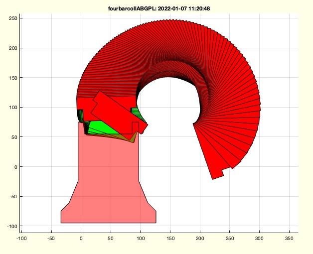 | % fourbarcollABGPL(CPLW,A0,B0,A1,B1,GPLA,GPLB,wlim,CPLE,limi) - returns the crank angle interval for an object liked to a Pose % (by Tim Lueth, VLFL-Lib, 2022-JAN-06 as class: KINEMATICS AND FRAMES) % % The 9th parameter is CPLE % The 10th parameter is limit; default is 0.01 (Status of: 2022-01-07) % % Introduced first in SolidGeometry 5.1 % % See also: CPLcrossCPLpathlimit % % wint=fourbarcollABGPL(CPLW,A0,B0,[A1,B1,GPLA,GPLB,wlim,CPLE,limi]) % === INPUT PARAMETERS === % CPLW: Static Obstacle % A0: A0 or Pose PS % B0: B0 or solution number % A1: A1 or empty if PS is used % B1: B1 or empty if PS is used % GPLA: GPLA or empty if PS is used % GPLB: GPLB or empty if PS is used % wlim: Angle limitation % === OUTPUT RESULTS ====== % wint: allowed angle interval without collision % % EXAMPLE: % PS=Posesample('Tiegel'); % PS.CPLM=PLtrans1(PLsquare(50,150))+[100 0]; fourBarposesyntheses(PS,[1 2],[10 5 5]); PSN=ans; % fourbarcollABGPL(PSN.CPLW,PSN,155,'','','','','','',0.005) % % % See also: CPLcrossCPLpathlimit % % % Copyright 2022 Tim C. Lueth |
Posestripfields(PS)- removes alls fields that seem results not conditions from pose synthesis fncts |
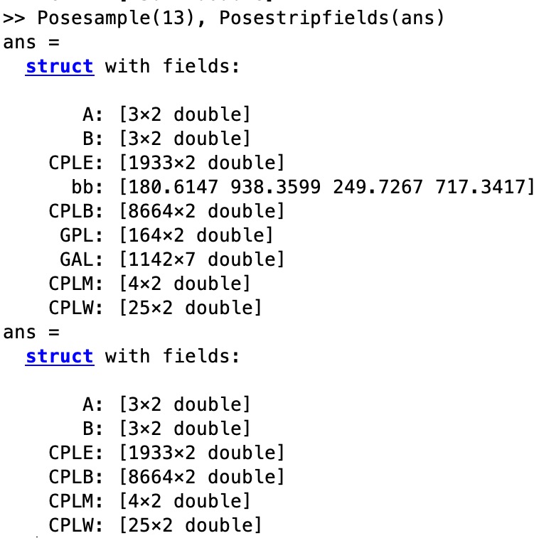 | % Posestripfields(PS) - removes alls fields that seem results not conditions from pose synthesis fncts % (by Tim Lueth, VLFL-Lib, 2022-JAN-03 as class: KINEMATICS AND FRAMES) % % macro for % PS=stripfields(PS,'A0','B0','A1','B1','GAL','BPL','A0L','B0L','solut',' % GPL','bb','psel'); % The fields % A and B for definiting Poses % CPLE as shape for the effector % CPLM for base point area % CPLW for restricted area % CPLB for background setches % cnstr for conditions % will remain (Status of: 2022-01-03) % % Introduced first in SolidGeometry 5.1 % % See also: stripfields % % PS=Posestripfields(PS) % === INPUT PARAMETERS === % PS: Any Pose struct. % === OUTPUT RESULTS ====== % PS: Struct without resulting fields % % EXAMPLE: % Posesample(13), Posestripfields(ans) % % See also: stripfields % % % Copyright 2022 Tim C. Lueth |
fourBarposesyntheses(PS,posel,grids,order,limit,cnstr)- fourbar pose synthesis |
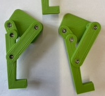 | % fourBarposesyntheses(PS,posel,grids,order,limit,cnstr) - fourbar pose synthesis % (by Tim Lueth, VLFL-Lib, 2022-JAN-01 as class: KINEMATICS AND FRAMES) % % This fnctn combines the individual solution procedures of single and % multi pose synthesis for 4R 4bar linkages, which already exist as % checkfourbar1poseattachpermutation, checkfourbar2poseattachpermutation, % checkfourbar3poseattachpermutation and can be controlled with the % fnctn checkfourbar123solutions. % (Status of: 2022-01-01) % % Introduced first in SolidGeometry 5.1 % % See also: checkfourbar1poseattachpermutation, % checkfourbar2poseattachpermutation, checkfourbar3poseattachpermutation, % checkfourbar123solutions, Posesample, fourBarposeplotsolution, % fourBarposelayering, fourBarCLLL2SGdesign % % PS=fourBarposesyntheses(PS,[posel,grids,order,limit,cnstr]) % === INPUT PARAMETERS === % PS: Pose struct including fields A, B, CPLE, CPLM, CPLW % posel: selected poses, number selects algorithm too % grids: grid point numbers for CPLE and CPLM % order: optional order of poses for ccw crank movement % limit: optional limitation at 1st or last pose % cnstr: optinal constraints for checkfourbar123solutions % === OUTPUT RESULTS ====== % PS: Pose including field "solut" with solutions % % See also: checkfourbar1poseattachpermutation, % checkfourbar2poseattachpermutation, checkfourbar3poseattachpermutation, % checkfourbar123solutions, Posesample, fourBarposeplotsolution, % fourBarposelayering, fourBarCLLL2SGdesign % % % Copyright 2022 Tim C. Lueth |
Poseplotsolution(PS,sel,show)- plots A0, B0, and geometry and animation of fourbar linkage design |
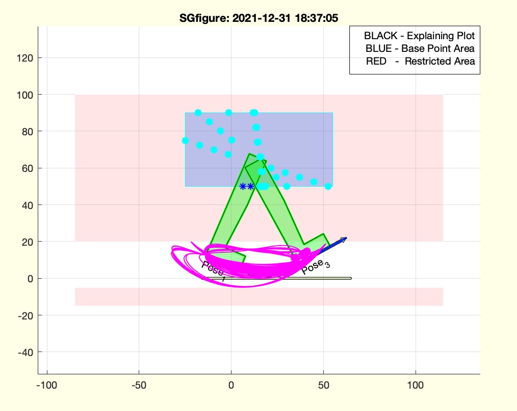 | % Poseplotsolution(PS,sel,show) - plots A0, B0, and geometry and animation of fourbar linkage design % (by Tim Lueth, VLFL-Lib, 2021-DEZ-31 as class: KINEMATICS AND FRAMES) % % uses "PLofFourbarcouplercurve" and "fourbarplotABGPL" (Status of: % 2021-12-31) % % Introduced first in SolidGeometry 5.1 % % See also: Poseplot, Poseplotspace, PoseplotA0B0 % % h=Poseplotsolution(PS,[sel,show]) % === INPUT PARAMETERS === % PS: Pose struct containing field "solut" % sel: number, sequence or constraint string to select; default is all % show: 'plotit', 'animat" "both" % === OUTPUT RESULTS ====== % h: handle to plot % % EXAMPLE: % PS=PosesampleWalk; % PS=checkfourbar2Poseattachpermutation(PS,[1 3],10); % PS=checkfourbar123solutions(PS,'isrot, break coll CPL0 CPLW'); % SGfigure; cla; Poseplotspace(PS); Poseplot(PS); Poseplotsolution(PS); delete(ans); % SGfigure; cla; Poseplotspace(PS); Poseplot(PS); Poseplotsolution(PS,25,'plotit'); delete(ans); % SGfigure; cla; Poseplotspace(PS); Poseplot(PS); Poseplotsolution(PS,25,'animate'); delete(ans); % % % See also: Poseplot, Poseplotspace, PoseplotA0B0 % % % Copyright 2021-2022 Tim C. Lueth |
checkfourbar123solutions(PS,cnstr,grdnx,show)- just checks an limits solutions of 1-2-3 Pose syntheses |
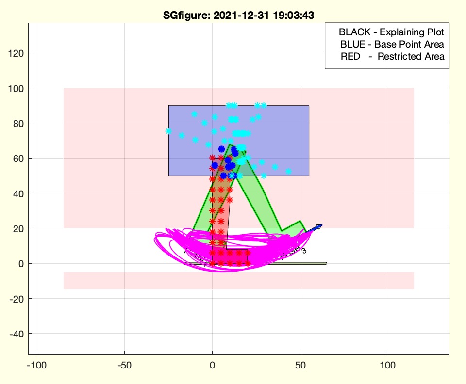 | % checkfourbar123solutions(PS,cnstr,grdnx,show) - just checks an limits solutions of 1-2-3 Pose syntheses % (by Tim Lueth, VLFL-Lib, 2021-DEZ-31 as class: KINEMATICS AND FRAMES) % % The field solut has the follwing structure: % [A0 B0 A1 B1 GPLA GPLB wlim ord nan nan nan] % % THe concept was first used in checkfourbar1Poseattachpermutation, but % has been extracted to be used by alle (Status of: 2021-12-31) % % Introduced first in SolidGeometry 5.1 % % See also: checkfourbar1Poseattachpermutation, % checkfourbar2Poseattachpermutation, checkfourbar3Poseattachpermutation % % PS=checkfourbar123solutions(PS,[cnstr,grdnx,show]) % === INPUT PARAMETERS === % PS: Pose struct with fields CPLM, CPLE, CPLW, AND solut % cnstr: constraints such as "ISROT" % grdnx: % show: 'plot', 'animat', 'both' % === OUTPUT RESULTS ====== % PS: Pose struct with reduced number of solutions % % EXAMPLE: % PS=PosesampleWalk; % PS=checkfourbar2Poseattachpermutation(PS,[1 3],10); % checkfourbar123solutions(PS,'isrot, break coll CPL0 CPLW'); PSN=ans; % SGfigure; cla; Poseplotspace(PS); Poseplot(PS); Poseplotsolution(PSN); % % See also: checkfourbar1Poseattachpermutation, % checkfourbar2Poseattachpermutation, checkfourbar3Poseattachpermutation % % % Copyright 2021 Tim C. Lueth |
CPLrack4PL(PL,b,t)- returns a contour for rack that can be used as rack (ground link for linkages) |
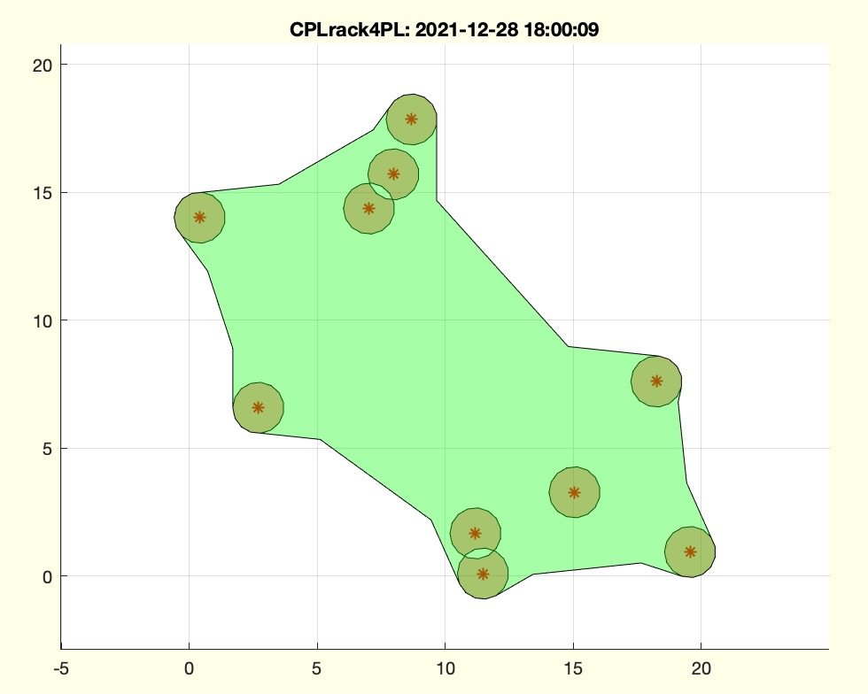 | % CPLrack4PL(PL,b,t) - returns a contour for rack that can be used as rack (ground link for linkages) % (by Tim Lueth, VLFL-Lib, 2021-DEZ-28 as class: CLOSED POLYGON LISTS) % % Introduced first in SolidGeometry 5.1 % % See also: CPLconvexhullfillgap, CPLextendbyPL, CPLrackPLdelaunay, % CPLofspokedPL % % CPLF=CPLrack4PL([PL,b,t]) % === INPUT PARAMETERS === % PL: Point list such as [A0;B0] % b: buffer; distance required to implement a revolute joint % t: 'minimal', 'circ' or 'box', 'delaunay', 'spokes'; default is 'min' % === OUTPUT RESULTS ====== % CPLF: Contour to carry revolute joints for linkages % % EXAMPLE: % CPLrack4PL(20*rand(10,2),1,'min'); % CPLrack4PL(PLsample(12),1,'box'); % CPLrack4PL(PLsample(12),1,'min'); % CPLrack4PL(PLsample(12),1,'circ'); % CPLrack4PL(PLsample(12),1,'bar'); % CPLrack4PL(PLsample(12),1,'spoke'); % % See also: CPLconvexhullfillgap, CPLextendbyPL, CPLrackPLdelaunay, % CPLofspokedPL % % % Copyright 2021-2022 Tim C. Lueth |
SGpinshaft(r,d,b)- creates a pin using PLshaftrad |
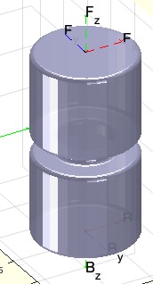 | % SGpinshaft(r,d,b) - creates a pin using PLshaftrad % (by Tim Lueth, VLFL-Lib, 2021-DEZ-28 as class: PARAMETRIC DESIGN) % % will be modified using PLshaftrad instead of PLshaf % % (Status of: 2022-01-16) % % Introduced first in SolidGeometry 5.1 % % See also: SGpincountersink, SGpindowel, SGpinring, SGpinringtail, % SGpintorquegauge, SGpinwrenchsize, SGiqpin, SGsbpin % % SG=SGpinshaft([r,d,b]) % === INPUT PARAMETERS === % r: Radius per step % d: distance between steps % b: Radius for broken edges; see also PLradialEdges % === OUTPUT RESULTS ====== % SG: Solid Geometry % % EXAMPLE: % SGpinshaft([6 3 6],[10 2 10],[.5 0]) % % % See also: SGpincountersink, SGpindowel, SGpinring, SGpinringtail, % SGpintorquegauge, SGpinwrenchsize, SGiqpin, SGsbpin % % % Copyright 2021-2022 Tim C. Lueth |
exp_2021_12_27_walk(PS)- example to learn how to desgin a real walking machine |
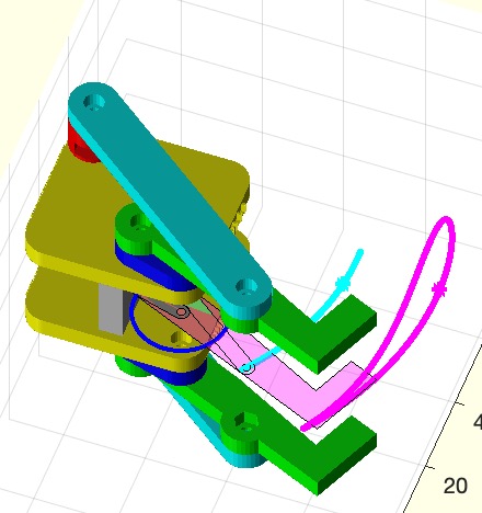 | % exp_2021_12_27_walk(PS) - example to learn how to desgin a real walking machine % (by Tim Lueth, VLFL-Lib, 2021-DEZ-27 as class: EXPERIMENTS) % % The walking machine is designed as an STL file for printing with a 3D % printer. It is mounted with screws and nuts of DIN 912 and 985. To % achieve the fits for the respective 3D printer, the printer must be % selected with the slfit fnctn. (Status of: 2022-01-01) % % Introduced first in SolidGeometry 5.1 % % See also: PosesampleWalk, checkfourbar1Poseattachpermutation % % PS=exp_2021_12_27_walk([PS]) % === INPUT PARAMETERS === % PS: Pose created by checkfourbar1Poseattachpermutation; default is % automatic % === OUTPUT RESULTS ====== % PS: resulting pose % % EXAMPLE: % PosesampleWalk; PS=ans; % checkfourbar1Poseattachpermutation(PS,1,[20 2 2],'','isrot, break coll cplw CPL0, break length CPL0 < 120'); PS=ans; % ~ 3 Min % exp_2021_12_27_walk(PS); PS=ans; % PS as argument is not really required % % See also: PosesampleWalk, checkfourbar1Poseattachpermutation % % % Copyright 2021-2022 Tim C. Lueth |
SGfourbarlinkageA0B0DIN912985(CPL,wlim,R12o,PS,MM,MPL,FIX)- Designs a 4bar-Linkage as solid geometry |
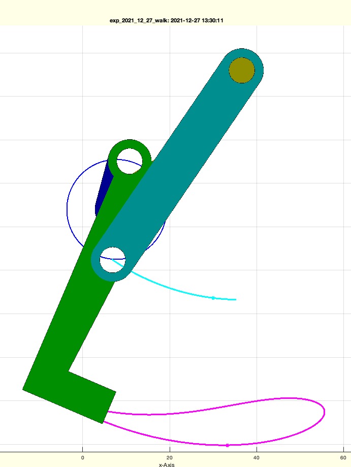 | % SGfourbarlinkageA0B0DIN912985(CPL,wlim,R12o,PS,MM,MPL,FIX) - Designs a 4bar-Linkage as solid geometry % (by Tim Lueth, VLFL-Lib, 2021-DEZ-27 as class: AUTOMATIC DESIGN) % % Since it is now clear to me, that 4 joint coordinates defined a unique % 4bar-linkage, it is possible to design a solid for % % See also fnctns of type SGiqXXXXXX % Geometry Styling see in fourbarplotABGPL % Prof. Dr. Hans-Dieter Burkhard % (Status of: 2021-12-31) % % Introduced first in SolidGeometry 5.1 % % See also: fourbarplotABGPL, checkfourbarsegment, PLofFourbarcouplercurve % % SGall=SGfourbarlinkageA0B0DIN912985(CPL,[wlim,R12o,PS,MM,MPL,FIX]) % === INPUT PARAMETERS === % CPL: [A0; B0; B1; A1; [GPLA GPLB]] to define the 4bar linkage | Nr of % PS.solut % wlim: angle limitatins; if empty the full intervall is used % R12o: Outer an inner radius for linkage [Rout Rin]; default is R12ofCPL % PS: Pose including fields CPLE % MM: [metrix diameter metric length overlap; default is [2.5 6 0] % MPL: Rack assembly point to add % FIX: fixation method '985' or 'bush' % === OUTPUT RESULTS ====== % SGall: {SGC,SGE,SGS,SGG,SG0} % % % EXAMPLE: % CPLfourbarcontour(100,80,100,40); CPL=ans; % SGfourbarlinkageA0B0DIN912985([CPL; -50 -30; +50 -30]) % SGfourbarlinkageA0B0DIN912985(CPLfourbarcontour([80,90,100,100])); SGALL=ans; % close all; SGfigure; SGplotcellmultiple(SGALL); shg; % SGfourbarlinkageA0B0DIN912985(32,'','',PS); % Use solution 32 of PS.solut % % % See also: fourbarplotABGPL, checkfourbarsegment, PLofFourbarcouplercurve % % % Copyright 2021-2022 Tim C. Lueth |
PoseplotA0B0(PS)- plots the existing solutions for A0 and B0 |
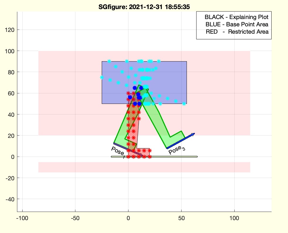 | % PoseplotA0B0(PS) - plots the existing solutions for A0 and B0 % (by Tim Lueth, VLFL-Lib, 2021-DEZ-26 as class: KINEMATICS AND FRAMES) % % A0 is blue % B0 is cyan colored (Status of: 2021-12-31) % % Introduced first in SolidGeometry 5.1 % % See also: Poseplot, Poseplotspace, Poseplotsolution % % h=PoseplotA0B0(PS) % === INPUT PARAMETERS === % PS: Pose struct including field 'solut' % === OUTPUT RESULTS ====== % h: handle to plot % % EXAMPLE: % PS=PosesampleWalk; % PS=checkfourbar2Poseattachpermutation(PS,[1 3],10); % PS=checkfourbar123solutions(PS,'isrot, break coll CPL0 CPLW'); % PoseplotA0B0(PS) % % See also: Poseplot, Poseplotspace, Poseplotsolution % % % Copyright 2021 Tim C. Lueth |
CPLextendbyPL(CPL,PL,lim,buf)- extends a CPL outline contour by some points |
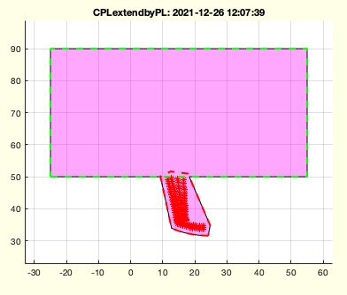 | % CPLextendbyPL(CPL,PL,lim,buf) - extends a CPL outline contour by some points % (by Tim Lueth, VLFL-Lib, 2021-DEZ-26 as class: CLOSED POLYGON LISTS) % % used in fourBarposesyntheses with constraint "EXTEND CPLM" (Status of: % 2022-01-09) % % Introduced first in SolidGeometry 5.1 % % See also: CPLadd, CPLaddauxpoints, CPLrack4PL % % CPLC=CPLextendbyPL(CPL,PL,[lim,buf]) % === INPUT PARAMETERS === % CPL: Exisintg CPL % PL: New Points % lim: limit until extension default is s % buf: buffer arount PL; default is s/10 % === OUTPUT RESULTS ====== % CPLC: New Contour % % EXAMPLE: % CPLextendbyPL(CPLsample(6),[-10 -10],'',1) % CPLextendbyPL(CPLsample(12),[-10 -10],'',1) % % See also: CPLadd, CPLaddauxpoints, CPLrack4PL % % % Copyright 2021-2022 Tim C. Lueth |
figcopyright(cname)- draws a copyright marker inside of the current figure |
 | % figcopyright(cname) - draws a copyright marker inside of the current figure % (by Tim Lueth, VLFL-Lib, 2021-DEZ-26 as class: VISUALIZATION) % % Introduced first in SolidGeometry 5.1 % % See also: username, pixelofaxis, SGfigurefooter % % [h,lc]=figcopyright([cname]) % === INPUT PARAMETERS === % cname: copyright owner; default is user name % === OUTPUT RESULTS ====== % h: handle to the text % lc: position if text in gca % % EXAMPLE: % clf; figcopyright; shg % clf; figcopyright(' by Franz Irlinger'); shg % % See also: username, pixelofaxis, SGfigurefooter % % % Copyright 2021-2022 Tim C. Lueth |
SGfigurefooter(textstr)- plots a footer into the window |
 | % SGfigurefooter(textstr) - plots a footer into the window % (by Tim Lueth, VLFL-Lib, 2021-DEZ-25 as class: VISUALIZATION) % % Introduced first in SolidGeometry 5.1 % % See also: figcopyright % % h=SGfigurefooter(textstr) % === INPUT PARAMETERS === % textstr: textstring for footer % === OUTPUT RESULTS ====== % h: handle to text % % EXAMPLE: % clf; figcopyright(' by Franz Moser'); shg, SGfigurefooter('This is a test'); % % See also: figcopyright % % % Copyright 2021-2022 Tim C. Lueth |
getPoseconstraintvalue(PS,tags2find)- returns wether a condition string is used within a Pose field |
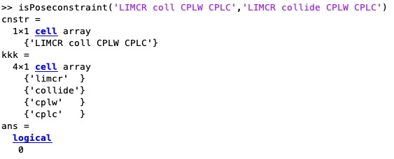 | % getPoseconstraintvalue(PS,tags2find) - returns wether a condition string is used within a Pose field % (by Tim Lueth, VLFL-Lib, 2021-DEZ-25 as class: KINEMATICS AND FRAMES) % % % THERE IS NO SYNTAX CHECK yet % % break length CPL0 within [1000 2000] % (Status of: 2021-12-25) % % Introduced first in SolidGeometry 5.1 % % See also: PosesampleCover, isPoseconstraint % % found=getPoseconstraintvalue(PS,[tags2find]) % === INPUT PARAMETERS === % PS: Pose including a field "cnstr" for constraints OR string % tags2find: condition string to find a value constraint % === OUTPUT RESULTS ====== % found: true or false or a value % % EXAMPLE: % getPoseconstraintvalue('isrot, break length CPL0 > [1000 2000]','break length CPL0 >') % finds [1000 2000] % getPoseconstraintvalue('isrot, break length CPL0 > [1000 2000]','break length CPLW >') % returns false % getPoseconstraintvalue('isrot, break length CPL0 > [1000 2000]','length CPL0 >') % returns a string % % See also: PosesampleCover, isPoseconstraint % % % Copyright 2021 Tim C. Lueth |
CPLofPLcrossCPL(CPL,PL,LL)- cuts a line by crossings using a CPL |
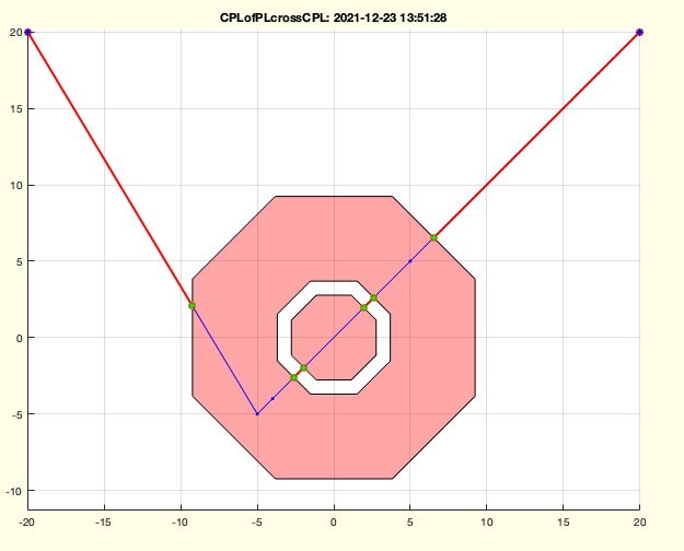 | % CPLofPLcrossCPL(CPL,PL,LL) - cuts a line by crossings using a CPL % (by Tim Lueth, VLFL-Lib, 2021-DEZ-22 as class: CLOSED POLYGON LISTS) % % works with CPLs % (Ugly Implementation but requrired for % checkfourbar1Poseattachpermutation (Status of: 2021-12-24) % % Introduced first in SolidGeometry 5.1 % % See also: crossC2P, isInteriorofCPL % % [NPL,FFL]=CPLofPLcrossCPL(CPL,PL,[LL]) % === INPUT PARAMETERS === % CPL: Closed Polygon line % PL: Point List % LL: Optional Length or angle list related to the points of PL % === OUTPUT RESULTS ====== % NPL: Point list separated by the crossing % FFL: Interpolated Value List % % EXAMPLE: % CPLofPLcrossCPL(PLcircle(10,8),[-15 -15;+15 -15]) % No crossing % CPLofPLcrossCPL(PLcircle(10,8),[-15 -15;+15 +15]) % Crossing % CPLofPLcrossCPL(CPLsample(13),[-15 -15;+15 +15]) % three crossings % CPLofPLcrossCPL(PLcircle([10,4,3],8),[-20 20;-5 -5; -4 -4; 5 5; 20 20]) % Crossing % CPLofPLcrossCPL(PLcircle([10,4,3],8),[-20 20;-5 -5; -4 -4; 5 5; 20 20],[0 9 0 0 9]) % interpolation % CPLofPLcrossCPL(PLcircle([10,4,3],8),[-20 20;-5 -5; -4 -4],[0 9 0]) % End in empty % % See also: crossC2P, isInteriorofCPL % % % Copyright 2021 Tim C. Lueth |
angleintersect(WINA,WINB)- intersect two angle areas |
 | % angleintersect(WINA,WINB) - intersect two angle areas % (by Tim Lueth, VLFL-Lib, 2021-DEZ-21 as class: ANALYTICAL GEOMETRY) % % isincirclesegment % angleshift % angleinterv % Even having the three fnctns, it is still always a challange to work % with the angle intervals (Status of: 2021-12-21) % % Introduced first in SolidGeometry 5.1 % % See also: isincirclesegment, angleshift, angleinterv % % % WINC=angleintersect(WINA,WINB) % === INPUT PARAMETERS === % WINA: angle interval A % WINB: angle interval B % === OUTPUT RESULTS ====== % WINC: Intersection of angle interval % % EXAMPLE: % angleintersect([3.6*pi 4.6*pi],[0 pi/6]+-pi+1.3) % NO OVERLAPP % angleintersect([3.6*pi 4.6*pi],[0 pi/6]+-pi+1.4) % right overlap % angleintersect([3.6*pi 4.6*pi],[0 pi/6]+-pi+2) % inside % angleintersect([3.6*pi 4.6*pi],[0 pi/6]+-pi+3) % inside % angleintersect([3.6*pi 4.6*pi],[0 pi/6]+-pi+4) % inside % angleintersect([3.6*pi 4.6*pi],[0 pi/6]+-pi+4.8) % left overlap % % See also: isincirclesegment, angleshift, angleinterv % % % % Copyright 2021 Tim C. Lueth |
isPoseconstraint(PS,cond)- returns wether a condition string is used within a Pose field |
 | % isPoseconstraint(PS,cond) - returns wether a condition string is used within a Pose field % (by Tim Lueth, VLFL-Lib, 2021-DEZ-20 as class: KINEMATICS AND FRAMES) % % % % LIMCR collision CPLW CPLC % % LIMCR collision CPLW CPLS % % BREAK collision CPLM CPLC % % BREAK collision CPLM CPLS % (Status of: 2021-12-20) % % Introduced first in SolidGeometry 5.1 % % See also: PosesampleCover, getPoseconstraintvalue % % found=isPoseconstraint(PS,[cond]) % === INPUT PARAMETERS === % PS: Pose including a field "cnstr" for constraints OR string % cond: condition string to find in constraint % === OUTPUT RESULTS ====== % found: true or false % % EXAMPLE: % isPoseconstraint(PosesampleCover,'LIMCR collision CPLW CPLC') % check finding in Pose constraints % isPoseconstraint(PosesampleCover,'LIMCR coll CPLW CPLM') % % isPoseconstraint('LIMCR coll CPLW CPLC','LIMCR coll CPLW CPLC') % Direct call with 2 strings % % See also: PosesampleCover, getPoseconstraintvalue % % % Copyright 2021 Tim C. Lueth |
fourbarplotABGPL(A0,B0,A1,B1,GPLA,GPLB,R12o,wlim,CPLE)- simply plots a fourbar linkage based on points - recommended in SG-Lib 5.1 |
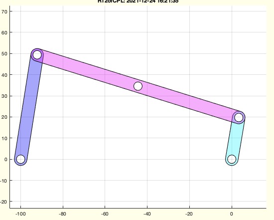 | % fourbarplotABGPL(A0,B0,A1,B1,GPLA,GPLB,R12o,wlim,CPLE) - simply plots a fourbar linkage based on points - recommended in SG-Lib 5.1 % (by Tim Lueth, VLFL-Lib, 2021-DEZ-19 as class: KINEMATICS AND FRAMES) % % Fnctn to explain the programming: (9th parameter is CPLE) % Any 4bar linkage that is defined by four joint coordinates is able to % execute a unique movement solution (in constrast to a 4bar linkage that % is defined by link length) in a specific elbow configuration and in the % right crank movement segment. By defining the attachment points A1 and % B1 relative to a Pose O0, also the shape of the coupler link is % defined. In case that link diameter and bire diameter are given, it is % possible to draw an linkage that can even extruded to a solid geometry. % % (Status of: 2021-12-24) % % Introduced first in SolidGeometry 5.1 % % See also: PLofFourbarcouplercurve, R12ofCPL, CPLfourbarcontour % % h=fourbarplotABGPL(A0,B0,A1,B1,[GPLA,GPLB,R12o,wlim,CPLE]) % === INPUT PARAMETERS === % A0: Base point of crank % B0: Base point of swing % A1: Attachment point of crank at coupler % B1: Attachment point of swing at coupler % GPLA: Position of attachment point A1 relativ to a pose % GPLB: Position of attachment point B1 relativ to a pose % R12o: R12ofCPL [Out and inner radius of link and bore] % wlim: if used, the movement path of crank, swing and pose are drawn % === OUTPUT RESULTS ====== % h: handle to the plot; % % EXAMPLE: % CPLfourbarcontour(100,20,100,50); CPL=ans; % R12ofCPL(CPL); % cla; fourbarplotABGPL(CPL(1,:), CPL(2,:), CPL(4,:), CPL(3,:)); % % % See also: PLofFourbarcouplercurve, R12ofCPL, CPLfourbarcontour % % % Copyright 2021 Tim C. Lueth |
R12ofCPL(CPL)- return standardized link and joint dimensions |
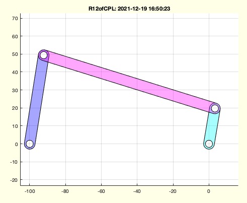 | % R12ofCPL(CPL) - return standardized link and joint dimensions % (by Tim Lueth, VLFL-Lib, 2021-DEZ-19 as class: CLOSED POLYGON LISTS) % % More or less for creating nice images and animations in 4bar linkage % synthesis (Status of: 2021-12-19) % % Introduced first in SolidGeometry 5.1 % % See also: fourbarplotABGPL % % R12o=R12ofCPL(CPL) % === INPUT PARAMETERS === % CPL: List of Points for A0, B0, B1, A1 % === OUTPUT RESULTS ====== % R12o: [Outer and Inner radius] for links % % EXAMPLE: % R12ofCPL(CPLfourbarcontour(100,20,100,50)) % CAll with length % % % See also: fourbarplotABGPL % % % Copyright 2021 Tim C. Lueth |
textadjust2gca (hh)- adjust text width to fit in gca |
 | % textadjust2gca (hh) - adjust text width to fit in gca % (by Tim Lueth, VLFL-Lib, 2021-DEZ-16 as class: USER INTERFACE) % % required for example in Videotitle if the title does not fit on the % screen width (Status of: 2021-12-17) % % Introduced first in SolidGeometry 5.1 % % See also: SGfigureeval, SGfigurepapermode, papermode, fontsize, % imageVideoTitle % % textadjust2gca(hh) % === INPUT PARAMETERS === % hh: handle to text % % EXAMPLE: % SGfigure; axis off; h=textP([-.2 0],'The quick brown fox jums over the lazy dog','','',32); % textadjust2gca(h) % % See also: SGfigureeval, SGfigurepapermode, papermode, fontsize, % imageVideoTitle % % % Copyright 2021 Tim C. Lueth |
PosesampleWalk- pose sample will be integrated into Posesample |
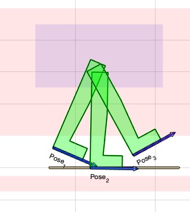 | % PosesampleWalk - pose sample will be integrated into Posesample % (by Tim Lueth, VLFL-Lib, 2021-DEZ-16 as class: KINEMATICS AND FRAMES) % % Posesample(12) % (Status of: 2022-01-16) % % Introduced first in SolidGeometry 5.1 % % See also: Posesample % % PS=PosesampleWalk % === OUTPUT RESULTS ====== % PS: Posesample(12) % % EXAMPLE: % PosesampleWalk; PS=ans; % % See also: Posesample % % % Copyright 2021-2022 Tim C. Lueth |
PosetransrelGPL(PS,ng,nn)- shifts the poses into an effector grid point |
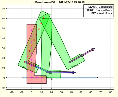 | % PosetransrelGPL(PS,ng,nn) - shifts the poses into an effector grid point % (by Tim Lueth, VLFL-Lib, 2021-DEZ-15 as class: KINEMATICS AND FRAMES) % % Introduced first in SolidGeometry 5.1 % % See also: PosetransrelCPLE, GPLauxgridpointsCPS2 % % % PS=PosetransrelGPL(PS,[ng,nn]) % === INPUT PARAMETERS === % PS: Pose % ng: optional number of grid points % nn: selected grid point; default is nearest % === OUTPUT RESULTS ====== % PS: Resulting Pose % % EXAMPLE: % PosetransrelGPL(Posesample(12)); % GPL unchanged, just shifted to nearest Grid point % PosetransrelGPL(Posesample(12),'','1); % GPL unchanged, just shifted to Grid point 1 % PosetransrelGPL(Posesample(12),30); % New GPL with 30 entries and nearst is selected % % See also: PosetransrelCPLE, GPLauxgridpointsCPS2 % % % % Copyright 2021 Tim C. Lueth |
attachmentpointsofA1B1TP(A1,B1,TP)- returns the grid points relative to effector from A1, B1 and a coordinate or pase |
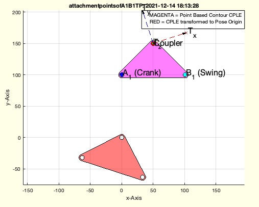 | % attachmentpointsofA1B1TP(A1,B1,TP) - returns the grid points relative to effector from A1, B1 and a coordinate or pase % (by Tim Lueth, VLFL-Lib, 2021-DEZ-14 as class: KINEMATICS AND FRAMES) % % Introduced first in SolidGeometry 5.1 % % See also: TofPoseattachmentpoints, CPLofA1B1P, TofA1B1GPL % % [GPA,GPB,TPP]=attachmentpointsofA1B1TP(A1,B1,TP) % === INPUT PARAMETERS === % A1: Position of A1 (Crank attachment point) % B1: Position of B1 (Follower attachment point) % TP: Pose or coordinate of coupler point % === OUTPUT RESULTS ====== % GPA: Relative grid position of Crank attachment to Effector pose % GPB: Relative grid position of follower attachment to Effector pose % TPP: Pose in case that a point was used % % EXAMPLE: % [GPA,GPB]=attachmentpointsofA1B1TP(A1,B1,TP) % PL=PLofFourbarcouplercurve(A0,B0,A1,B1,GPA,GPB,wlim,CPLE); % % % See also: TofPoseattachmentpoints, CPLofA1B1P, TofA1B1GPL % % % Copyright 2021 Tim C. Lueth |
angleinterv(wins,ival);- shifts an angle intervall table vainto a fixed interval such as [-pi..+pi] or [0 2*pi] |
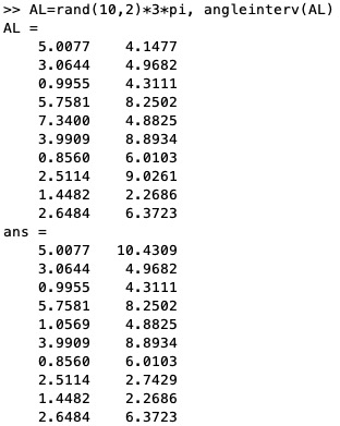 | % angleinterv(wins,ival); - shifts an angle intervall table vainto a fixed interval such as [-pi..+pi] or [0 2*pi] % (by Tim Lueth, VLFL-Lib, 2021-DEZ-14 as class: ANALYTICAL GEOMETRY) % % the second value is always in the interval [wins(i,1)+2*pi] % for i=1:size(wins,1) % wins(i,1)=angleshift(wins(i,1),ival); % wins(i,2)=angleshift(wins(i,2),wins(i,1)); %% shifted into the % array from wins(1)..wins(1)+2*pi % end % (Status of: 2021-12-14) % % Introduced first in SolidGeometry 5.1 % % See also: isincirclesegment, CPLcrosscircseg, angleshift, cplot % % wins=angleinterv(wins,[ival]); % === INPUT PARAMETERS === % wins: List of angle delta values [wmin wmax] % ival: [-pi..+pi] or [0 2*pi] % === OUTPUT RESULTS ====== % wins: Values of wins(:,1) in the allowed ival; no delta > 2*pi % % EXAMPLE: % AL=rand(10,2)*3*pi, angleinterv(AL) % % See also: isincirclesegment, CPLcrosscircseg, angleshift, cplot % % % Copyright 2021 Tim C. Lueth |
cplot(A0,wins,fc,fa,ec,lw)- Plots a list of circle segments |
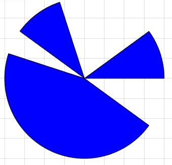 | % cplot(A0,wins,fc,fa,ec,lw) - Plots a list of circle segments % (by Tim Lueth, VLFL-Lib, 2021-DEZ-14 as class: ANALYTICAL GEOMETRY) % % dw=wins(:,2)-wins(:,1); s1=angleshift(wins(:,1)); wins=[s1 % s1+angleshift(dw)]; % (Status of: 2021-12-14) % % Introduced first in SolidGeometry 5.1 % % See also: isincirclesegment, CPLcrosscircseg, angleshift, angleinterv % % h=cplot([A0,wins,fc,fa,ec,lw]) % === INPUT PARAMETERS === % A0: Center and Radius of circle [x y R]; default is [0 0 1] % wins: [min max]; angle % fc: optional FaceColor % fa: optional FaceAlpha % ec: optional EdgeColor % lw: optional Edge Line Width % === OUTPUT RESULTS ====== % h: handle to go % % EXAMPLE: % SGfigure; cplot ([10 10 2],[0 0.2*pi; 0.6*pi 0.8*pi; 0.9*pi 1.8*pi]+2*pi,'b',1) % % See also: isincirclesegment, CPLcrosscircseg, angleshift, angleinterv % % % Copyright 2021 Tim C. Lueth |
angleshift(AL,ival)- shifts an agle value into a fixed interval such as [-pi..+pi] or [0 2*pi] |
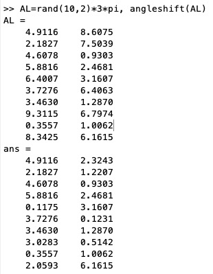 | % angleshift(AL,ival) - shifts an agle value into a fixed interval such as [-pi..+pi] or [0 2*pi] % (by Tim Lueth, VLFL-Lib, 2021-DEZ-14 as class: ANALYTICAL GEOMETRY) % % Introduced first in SolidGeometry 5.1 % % See also: isincirclesegment, CPLcrosscircseg, cplot, angleinterv % % AL=angleshift(AL,[ival]) % === INPUT PARAMETERS === % AL: List of angle values % ival: [-pi..+pi] or [0 2*pi]; or [ival ival+2*pi]; default is [0 2*pi] % === OUTPUT RESULTS ====== % AL: Alle values inside the allowed interval % % EXAMPLE: % AL=rand(10,2)*3*pi, % angleshift(AL) % angleshift(AL,[pi +pi) % [-pi ... pi] % angleshift(AL,[0 2*pi]) % [0 ...2*pi] % angleshift(AL,2) % [2 ... 2+2*pi] % % % See also: isincirclesegment, CPLcrosscircseg, cplot, angleinterv % % % Copyright 2021 Tim C. Lueth |
CPLcrosscircseg(CPLA,A0,wlim)- fnct to detect crossing segments of a circ line with a CPL |
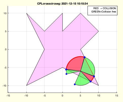 | % CPLcrosscircseg(CPLA,A0,wlim) - fnct to detect crossing segments of a circ line with a CPL % (by Tim Lueth, VLFL-Lib, 2021-DEZ-13 as class: ANALYTICAL GEOMETRY) % % Fnctn to detect crossing angles for crank and follower attchment point % path in fourbar linkage design tasks. Resolution is one degree; % Could be speed up by ray beam analysis instead of CPL subtraction % (Status of: 2021-12-15) % % Introduced first in SolidGeometry 5.1 % % See also: isincirclesegment, angleshift, angleinterv, cplot, % CPLofPLcrossCPL % % [wlim,winv]=CPLcrosscircseg([CPLA,A0,wlim]) % === INPUT PARAMETERS === % CPLA: CPL of restricted Area % A0: Center of circular movement % wlim: angle interval of circular movement; default is [0 2*pi] % === OUTPUT RESULTS ====== % wlim: list of crossed angle segments (right hand) % winv: inverse angle segments of wlim (right hand) % % EXAMPLE: % CPLcrosscircseg(CPLsample(3),[0 10 4 0.1]) % A0=[0 10] r=4; d=0.1 % CPLcrosscircseg(CPLsample(3),[0 10 4 0.1],[1.2*pi,2.4*pi]) % A0=[0 10] r=4; d=0.1 % CPLcrosscircseg(CPLsample(3),[0 -6 4 0.1],[1.2*pi,2.4*pi]) % A0=[0 10] r=4; d=0.1 % CPLcrosscircseg(CPLsample(3),[6 0 4 0.1],[1.2*pi,2.4*pi]) % A0=[0 10] r=4; d=0.1 % CPLcrosscircseg(CPLsample(3),[5 -6 4 0.1],[1.2*pi,2.9*pi]+pi/6) % % See also: isincirclesegment, angleshift, angleinterv, cplot, % CPLofPLcrossCPL % % % Copyright 2021 Tim C. Lueth |
dbpause(str,str2)- similar to pause, but shows the calling fnct and if dbprintmode is on, jumps to the line |
 | % dbpause(str,str2) - similar to pause, but shows the calling fnct and if dbprintmode is on, jumps to the line % (by Tim Lueth, VLFL-Lib, 2021-DEZ-12 as class: AUXILIARY PROCEDURES) % % Debug fnctn of Tim Lueth % dbprintf % dbpause % dbsave % dbreturn % dbprintmode % (Status of: 2021-12-23) % % Introduced first in SolidGeometry 5.1 % % See also: dbprintf, dbreturn, dbsave, dbprintmode % % % ch=dbpause([str,str2]) % === INPUT PARAMETERS === % str: string, if there is no time, or zero or seconds % str2: prompt if a time is used % === OUTPUT RESULTS ====== % ch: key character that was used in the graphics figure to continue % after pause % % See also: dbprintf, dbreturn, dbsave, dbprintmode % % % % Copyright 2021-2022 Tim C. Lueth |
PosetransrelCPLE(PS,TN)- shifts pose definition and CPLE using an HT transformation |
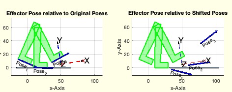 | % PosetransrelCPLE(PS,TN) - shifts pose definition and CPLE using an HT transformation % (by Tim Lueth, VLFL-Lib, 2021-DEZ-11 as class: KINEMATICS AND FRAMES) % % Currently just an educational fnctn and testing fuction to explain the % importance of the effector shape in contrast to the pose positions, % wich are useless without the effector pose relative to the poses % (Status of: 2021-12-11) % % Introduced first in SolidGeometry 5.1 % % See also: Posetransui, PosetransrelGPL % % PSN=PosetransrelCPLE(PS,[TN]) % === INPUT PARAMETERS === % PS: Pose with A and B and CPLE % TN: relative movement of the CPLE origin % === OUTPUT RESULTS ====== % PSN: Pose with shifted A and shifted B and shifted CPLE % % EXAMPLE: % PosetransrelCPLE(Posesample(12), TofR(rot(pi/20),[50 5])) % % % See also: Posetransui, PosetransrelGPL % % % Copyright 2021 Tim C. Lueth |
TofA1B1GPL(A1,B1,GPLA,GPLB)- Returns the Frame of the Pose wrt to |
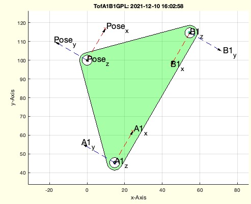 | % TofA1B1GPL(A1,B1,GPLA,GPLB) - Returns the Frame of the Pose wrt to % (by Tim Lueth, VLFL-Lib, 2021-DEZ-10 as class: KINEMATICS AND FRAMES) % % TofPose - Frame of A1 from Point A1 and B1 % TofPoseGPL - Frames of A1 and B1 from Pose and GPL % TofA1B1GPL - Frame of Pose from A1 and B1 and GPL % TofPoseattachmentpoints - Frames of B1 and A1 from Pose qnd Points A1 % and B1 % Links: Crank (Kurbel), follower (Swing, Rocker), coupler (Koppel), % ground link; % ground base points (Gestellpunkte), attachment points (Anlenkpunkte) % (Status of: 2021-12-16) % % Introduced first in SolidGeometry 5.1 % % See also: TofPoseGPL, TofPose, TofPoseattachmentpoints, CPLofA1B1P, % attachmentpointsofA1B1TP % % [TP,TA1,TB1]=TofA1B1GPL([A1,B1,GPLA,GPLB]) % === INPUT PARAMETERS === % A1: Attachment Point A1 in Space % B1: Attachment Point B1 in Space % GPLA: Attachment Point A1 on Effector % GPLB: Attachment Point B1 on Effector % === OUTPUT RESULTS ====== % TP: Pose in Space % TA1: Fram A1 in Space % TB1: Fram B1 in Space % % EXAMPLE: % T=TofR(rot(pi/3),[0 100]); GPLA=[-40 -40], GPLB=[40,-40], A1=PLtransT(GPLA,T);B1=PLtransT(GPLB,T); % TofA1B1GPL(A1,B1,GPLA,GPLB) % % See also: TofPoseGPL, TofPose, TofPoseattachmentpoints, CPLofA1B1P, % attachmentpointsofA1B1TP % % % Copyright 2021 Tim C. Lueth |
VLnearestNeighbor(VL1,VL2)- returns the nearest points in VL1 to the points in VL2 |
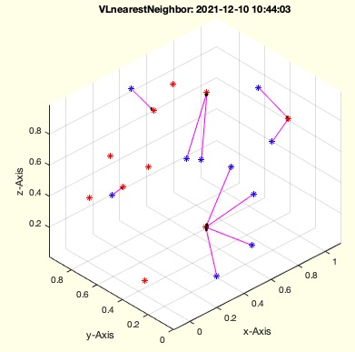 | % VLnearestNeighbor(VL1,VL2) - returns the nearest points in VL1 to the points in VL2 % (by Tim Lueth, VLFL-Lib, 2021-DEZ-10 as class: VERTICES / CLOUDS) % % Introduced first in SolidGeometry 5.1 % % See also: nearestpair, nearestcluster, PLcorrelate, VLcorrelate % % nn=VLnearestNeighbor(VL1,VL2) % === INPUT PARAMETERS === % VL1: Vertex list or Point List [m x 3] % VL2: Vertex list or Point List [n x 3] % === OUTPUT RESULTS ====== % nn: Index in VL1 which is nearest to VL2 [n x 1] % % EXAMPLE: % VLnearestNeighbor(rand(10,2),rand(10,2)) % VLnearestNeighbor(rand(10,3),rand(10,3)) % % % See also: nearestpair, nearestcluster, PLcorrelate, VLcorrelate % % % Copyright 2021 Tim C. Lueth |
GPLauxgridpointsCPS2(CPLR,nr);- creates a defined number of Gridpoints |
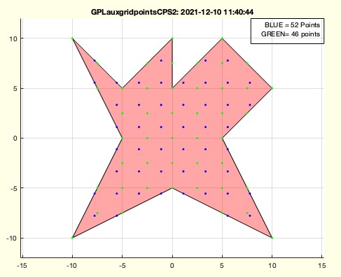 | % GPLauxgridpointsCPS2(CPLR,nr); - creates a defined number of Gridpoints % (by Tim Lueth, VLFL-Lib, 2021-DEZ-10 as class: CLOSED POLYGON LISTS) % % In contrast to GPLauxgridpointsCPS, this fnctn limits the number of % grid points (Status of: 2021-12-10) % % Introduced first in SolidGeometry 5.1 % % See also: GPLauxgridpointsCPS, GPLofPoseCPL % % [GPL2,d2,GPL1]=GPLauxgridpointsCPS2(CPLR,[nr]); % === INPUT PARAMETERS === % CPLR: Contour % nr: number of points to fill in; % === OUTPUT RESULTS ====== % GPL2: Grid Point list, size is smaller or equal as nr % d2: used distance % GPL1: smallest gridpoint list with more than nr points % % EXAMPLE: % GPLauxgridpointsCPS2(CPLsample(3),55); size(ans,1) % % See also: GPLauxgridpointsCPS, GPLofPoseCPL % % % Copyright 2021 Tim C. Lueth |
screencapture(scsize)- returns the full screen as frame, i.e. also confidential inforamtion in other applications |
 | % screencapture(scsize) - returns the full screen as frame, i.e. also confidential inforamtion in other applications % (by Matlab-CENTRAL, VLFL-Lib, 2021-DEZ-10 as class: USER INTERFACE) % % Handle with care, since it is possible to send data using matlab % On the other hand, it is also possible to readout the commandwindow and % editorscren if undocked which can be used for lectures too (Status of: % 2021-12-10) % % See also: getframe, figsetsize, SGprintgcf % % imgData=screencapture([scsize]) % === INPUT PARAMETERS === % scsize: [start end cols rows]; default is get(0,'ScreenSize'); % === OUTPUT RESULTS ====== % imgData: rows x cols x 3 as uint8 % % EXAMPLE: Just call % screencapture; % I=screencapture; whos I % screencapture([10 10 20 20 ]); whos ans % % % See also: getframe, figsetsize, SGprintgcf % |
PosesampleCover- creates a pose struct sample for a box hinge lid |
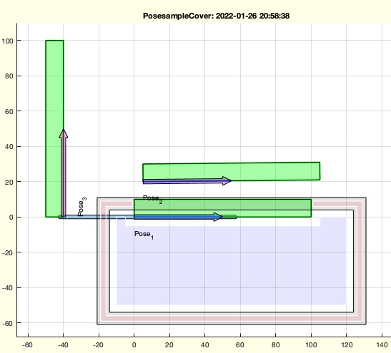 | % PosesampleCover - creates a pose struct sample for a box hinge lid % (by Tim Lueth, VLFL-Lib, 2021-DEZ-09 as class: KINEMATICS AND FRAMES) % % Introduced first in SolidGeometry 5.1 % % See also: PosesampleCover, PosesampleWalk, Posesample % % PS=PosesampleCover % === OUTPUT RESULTS ====== % PS: Pose sample for a box hinge lid % % See also: PosesampleCover, PosesampleWalk, Posesample % % % Copyright 2021-2022 Tim C. Lueth |
PoseaddGPL(PS,nr,bf,fl)- creates a Grid inside/on a contour |
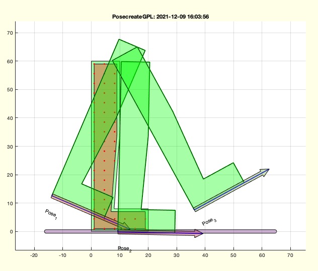 | % PoseaddGPL(PS,nr,bf,fl) - creates a Grid inside/on a contour % (by Tim Lueth, VLFL-Lib, 2021-DEZ-09 as class: CLOSED POLYGON LISTS) % % Introduced first in SolidGeometry 5.1 % % See also: checkfourbar3Poseattachpermutation, % checkfourbar2Poseattachpermutation, checkfourbar1Poseattachpermutation, % Poseplot, Poseplotspace % % PS=PoseaddGPL(PS,[nr,bf,fl]) % === INPUT PARAMETERS === % PS: Pose with Contour CPLE % nr: Number of Grid points to be achieved % bf: distance to outer contour; default is 0; % fl: if false; the conotur is filled; default is false % === OUTPUT RESULTS ====== % PS: Pose with CPLE and GPL % % EXAMPLE: % PS.CPLE=CPLsample(3); PoseaddGPL(PS,60,1); % PoseaddGPL(Posesample(12),60,1); Poseplot(Posesample(12)); % PS=Posesample(1), PoseaddGPL(PS,30); Poseplot(PS) % % See also: checkfourbar3Poseattachpermutation, % checkfourbar2Poseattachpermutation, checkfourbar1Poseattachpermutation, % Poseplot, Poseplotspace % % % Copyright 2021-2022 Tim C. Lueth |
SGreadstructfile(fname)- Reads in an matlab struct from an ascii struct file |
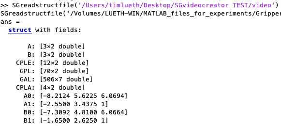 | % SGreadstructfile(fname) - Reads in an matlab struct from an ascii struct file % (by Tim Lueth, VLFL-Lib, 2021-DEZ-08 as class: FILE HANDLING) % % ## % # % % % % (extracted from PosereadAPD, 2019-02-15) % All files with ending APD (ascci pose definition) are ascii struct files % (Status of: 2021-12-08) % % Introduced first in SolidGeometry 5.1 % % See also: PosereadAPD, readtextfile % % [PS,fname]=SGreadstructfile([fname]) % === INPUT PARAMETERS === % fname: filename of the struct % === OUTPUT RESULTS ====== % PS: Struct % fname: used filename % % EXAMPLE: File format: % ## Comment % # A % 5, 5, 6 % # B % 6, 6 % 7, 7 % # C % Dies ist ein Test % % See also: PosereadAPD, readtextfile % % % Copyright 2021 Tim C. Lueth |
createvideoscript(fname)- fnct to create video tutorials of text, videos, figures |
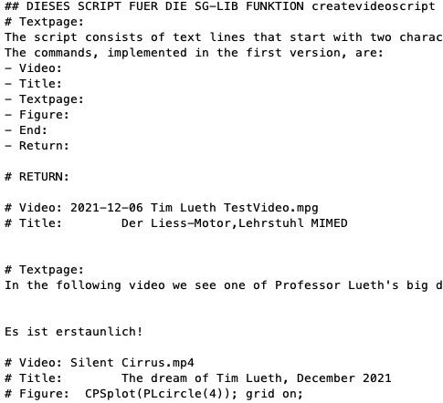 | % createvideoscript(fname) - fnct to create video tutorials of text, videos, figures % (by Tim Lueth, VLFL-Lib, 2021-DEZ-08 as class: VIDEO/AUDIO/PDF) % % WARNING ALL FILES WITH NAME "ZZVIDEO_" % Often in teaching figures or animations are made using matlab. Thoses % videos are uploaded to youtube or another video repository. Students % can easlity learn from videos by using the play and stop fnctn of a % player and often no audio is required if text pages are used. On the % other hand, creating videos is extremly time consuming. This fnctn % helps to make small clips explaining topics. % The basic commands in the script file are % ## Comment line % # Textpage: with following text files % # Video: % # Image: % # Title: < Title >, < subtitle >, < author-and-date > % # Figure: % # End: % # RETURN: just for debugging, stops the execution of the script % (Status of: 2021-12-09) % % Introduced first in SolidGeometry 5.1 % % See also: drawnowvid, Videoquickcloseandopen, Videoquickwritetextpage, % Videoquickstart, Videoquickwritegcf % % createvideoscript([fname]) % === INPUT PARAMETERS === % fname: filename of script file % % EXAMPLE: Create a directory and use a ascii textfile, for example videoscript.txt that uses the % commands mentioned above! Such as: % ## written by firstname lastname 2021-12-09 % # VIDEO: % # TITLE: My video title % # TEXTPAGE: % Hello Line 1 % Hello Line 2 % # END: % % See also: drawnowvid, Videoquickcloseandopen, Videoquickwritetextpage, % Videoquickstart, Videoquickwritegcf % % % Copyright 2021 Tim C. Lueth |
checkfourbar1Poseattachpermutation(PS,psel,grdnx,solu,cnstr)- Performs a fourbar-linkage syntheses based on ONE defined Pose |
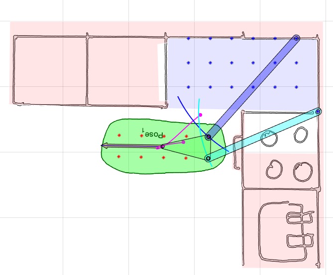 | % checkfourbar1Poseattachpermutation(PS,psel,grdnx,solu,cnstr) - Performs a fourbar-linkage syntheses based on ONE defined Pose % (by Tim Lueth, VLFL-Lib, 2021-DEZ-06 as class: KINEMATICS AND FRAMES) % % In the SG-Lib exist, there exist % checkfourbar3Poseattachpermutation - 3 Poses plus Effector Grid Points % checkfourbar2Poseattachpermutation - 2 Poses plus Effector Grid Points % plus Base Area Grid Points % checkfourbar1Poseattachpermutation - 1 Pose plus Effector Grid Points % plus Base Area Grid Points plus Pose contour shape % % CONSTRAINTS SUCH AS % "NOROT" OR "ISROT" % "LIMCR COLL CPLM CPLC" % (Status of: 2021-12-20) % % Introduced first in SolidGeometry 5.1 % % See also: isincirclesegment, Posefourbarplotcouplercurve, % checkfourbar2Poseattachpermutation, checkfourbar3Poseattachpermutation, % PosecreateGPL % % PS=checkfourbar1Poseattachpermutation(PS,[psel,grdnx,solu,cnstr]) % === INPUT PARAMETERS === % PS: Pose struct including CPLE, A, B % psel: selector of pose % grdnx: [grid nr, link radius, effector radius]; default [30 2.5 0.1] % solu: [A0i B0i A1i B1i] in CPLM and CPLE, if negative animated % cnstr: optional constraint string % === OUTPUT RESULTS ====== % PS: Pose struct % % EXAMPLE: % PS=PosesampleCover, PosecreateGPL(PS,30); Poseplot(PS); % checkfourbar1Poseattachpermutation(PS,1) % checkfourbar1Poseattachpermutation(PS,30) % checkfourbar1Poseattachpermutation(PS,1,30,[1 2 26 24) % % % See also: isincirclesegment, Posefourbarplotcouplercurve, % checkfourbar2Poseattachpermutation, checkfourbar3Poseattachpermutation, % PosecreateGPL % % % Copyright 2021-2022 Tim C. Lueth |
drawnowvid()- this fnct is an auxilary fnct to automate the creation of videos |
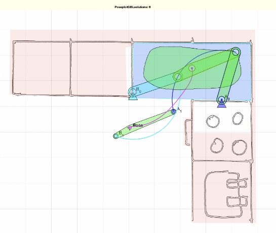 | % drawnowvid() - this fnct is an auxilary fnct to automate the creation of videos % (by Tim Lueth, VLFL-Lib, 2021-DEZ-06 as class: VISUALIZATION) % % If animations are created typically the drawnow fnctn is used to update % the screen. If later there is an idea to create videos from those % fnctn, it is possible to change the fnctn by inserting % Videoquickwritegcf or more easy to replace the drawnow fnctn by % drawnowvid. If there is no valid video writer, the fnctns is just % drawnow; in case that there is an open Vieowrite by Videoquickstart, a % snapshot is writen into the video. % % if Videoquickwritegcf fails within this fnctn, global Videoquick_vw is % set to [] (Status of: 2021-12-06) % % Introduced first in SolidGeometry 5.1 % % See also: Videoquickwritetextpage, Videoquickstart, % Videoquickcloseandopen, Videoquickwritegcf % % drawnowvid([]) % % See also: Videoquickwritetextpage, Videoquickstart, % Videoquickcloseandopen, Videoquickwritegcf % % % Copyright 2021 Tim C. Lueth |
figsize(sz)- sets the figure size |
 | % figsize(sz) - sets the figure size % (by Tim Lueth, VLFL-Lib, 2021-DEZ-06 as class: VISUALIZATION) % % For some video recordings it is necessary that the recorded figure % using getframe(gcf) has a defined size (Status of: 2021-12-06) % % Introduced first in SolidGeometry 5.1 % % See also: fullview, Videoquickwritetextpage, fontsize, papermode % % [nsz]=figsize([sz]) % === INPUT PARAMETERS === % sz: desired size; default is [960 540] % === OUTPUT RESULTS ====== % [nsz]: new size % % EXAMPLE: % close all; SGfigure; set(gcf,'Position',[400 400 400 400]); pause; figsize([3000 100]) % close all; SGfigure; set(gcf,'Position',[400 400 400 400]); pause; figsize % getframe(gcf) % % % See also: fullview, Videoquickwritetextpage, fontsize, papermode % % % Copyright 2021 Tim C. Lueth |
popgcf- remains only the remembered graphics object in the current figure |
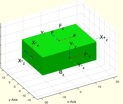 | % popgcf - remains only the remembered graphics object in the current figure % (by Tim Lueth, VLFL-Lib, 2021-DEZ-05 as class: VISUALIZATION) % % ..useful if the recording of all handles is not possible (Status of: % 2021-12-05) % % Introduced first in SolidGeometry 5.1 % % See also: copyfig, copygo, pastego, pushgcf % % popgcf % % EXAMPLE: % SGfigure; SGbox; pushgcf; CPSplot(PLcircle(30)); pause(1); popgcf; % % See also: copyfig, copygo, pastego, pushgcf % % % Copyright 2021 Tim C. Lueth |
pushgcf- remembers all graphics object in the current figure; |
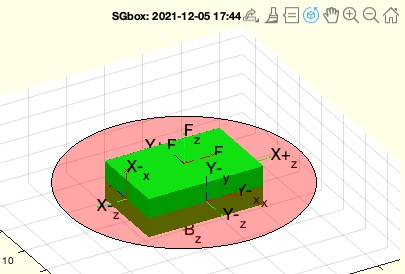 | % pushgcf - remembers all graphics object in the current figure; % (by Tim Lueth, VLFL-Lib, 2021-DEZ-05 as class: VISUALIZATION) % % ..useful if the recording of all handles is not possible (Status of: % 2021-12-05) % % Introduced first in SolidGeometry 5.1 % % See also: copyfig, copygo, pastego, popgcf % % pushgcf % % EXAMPLE: % SGfigure; SGbox; pushgcf; CPSplot(PLcircle(30)); pause(1); popgcf; % % See also: copyfig, copygo, pastego, popgcf % % % Copyright 2021 Tim C. Lueth |
CPLcrossline(CPL,PL,acc);- calculates the intersection of a CPL with a line |
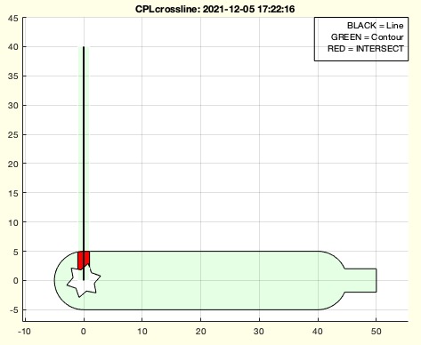 | % CPLcrossline(CPL,PL,acc); - calculates the intersection of a CPL with a line % (by Tim Lueth, VLFL-Lib, 2021-DEZ-05 as class: CLOSED POLYGON LISTS) % % Introduced first in SolidGeometry 5.1 % % See also: crossC2P, CPLofPLcrossCPL % % CPLX=CPLcrossline(CPL,PL,[acc]); % === INPUT PARAMETERS === % CPL: CLosed polygon region % PL: Point list % acc: accuracy, line thickness; default is 0.01 % === OUTPUT RESULTS ====== % CPLX: Crossing Area % % EXAMPLE: % CPLcrossline(CPLsample(37),[0 0;0 10],1) % % See also: crossC2P, CPLofPLcrossCPL % % % Copyright 2021 Tim C. Lueth |
TofPoseGPL(TP,A1,B1,CD)- returns the frames for A1 and B1 from a Pose and 2 GPL attachment points |
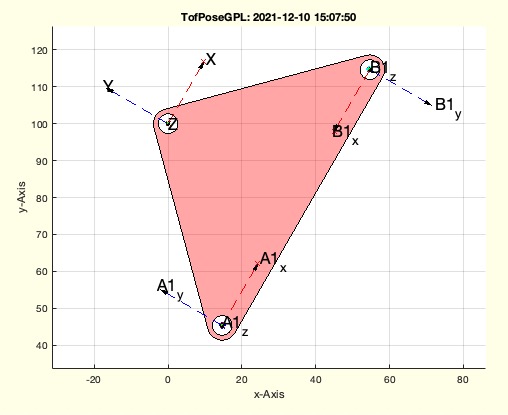 | % TofPoseGPL(TP,A1,B1,CD) - returns the frames for A1 and B1 from a Pose and 2 GPL attachment points % (by Tim Lueth, VLFL-Lib, 2021-DEZ-05 as class: KINEMATICS AND FRAMES) % % TofPose - Frame of A1 from Point A1 and B1 % TofPoseGPL - Frames of A1 and B1 from Pose and GPL % TofA1B1GPL - Frame of Pose from A1 and B1 and GPL % TofPoseattachmentpoints - Frames of B1 and A1 from Pose qnd Points A1 % and B1 % (Status of: 2021-12-10) % % Introduced first in SolidGeometry 5.1 % % See also: TofPoseGPL, TofPose, TofA1B1GPL, TofPoseattachmentpoints % % [TA1,TB1,TP]=TofPoseGPL([TP,A1,B1,CD]) % === INPUT PARAMETERS === % TP: World frame of Pose % A1: Point A1 in GPL % B1: Point B1 in GPL % CD: CODE for meaning of A1 and B1 'GLP' % === OUTPUT RESULTS ====== % TA1: World frame of A1 % TB1: World frame of B1 % TP: World frame of Pose % % EXAMPLE: % TofPoseGPL( TofR(rot(pi/3),[0 100]),[-40 -40],[40,-40],'GPL->A1B1') % Position and Rotation % TofPoseGPL( [0 100],[-40 -40],[40,-40],'GPL->A1B1') % Position and no rotation % TofPoseGPL( [0 100],[-40 -40],[40,-40]) % Position and no rotation % % See also: TofPoseGPL, TofPose, TofA1B1GPL, TofPoseattachmentpoints % % % Copyright 2021 Tim C. Lueth |
PoseplotGBLsolutions(PS,ul,an)- plots an individual solution of a 2 Pose syntheses (Field GBL) |
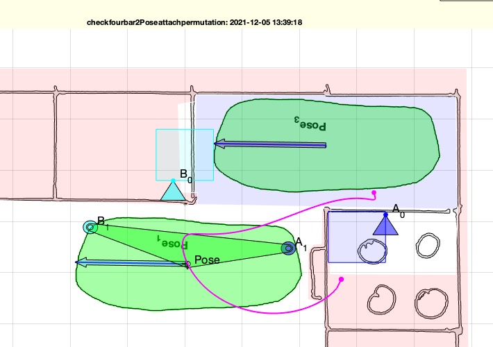 | % PoseplotGBLsolutions(PS,ul,an) - plots an individual solution of a 2 Pose syntheses (Field GBL) % (by Tim Lueth, VLFL-Lib, 2021-DEZ-05 as class: KINEMATICS AND FRAMES) % % ======================================================================= % OBSOLETE (2021-12-31) - USE 'Poseplotsolution' INSTEAD % ======================================================================= % % Developed for checking the plausibility during testing if fnctn % checkfourbar2Poseattachpermutation (Status of: 2021-12-05) % % Introduced first in SolidGeometry 5.1 % % See also: [ Poseplotsolution ] ; checkfourbar2Poseattachpermutation % % [h,PL]=PoseplotGBLsolutions(PS,[ul,an]) % === INPUT PARAMETERS === % PS: Pose struct include GBL solutions and psel % ul: solution indices to plot from GBP % an: if true; the solution is also animated % === OUTPUT RESULTS ====== % h: handle to drawing % PL: Point list of last solution % % EXAMPLE: % PosereadAPD('/Volumes/LUETH-WIN/MATLAB_files_for_experiments/basecabinet_new.APD');PS=ans; % PS=checkfourbar2Poseattachpermutation(PS,[1 3]); PS=ans; % ANALYZE % PoseplotGBLsolutions(PS,386) % % See also: [ Poseplotsolution ] ; checkfourbar2Poseattachpermutation % % % Copyright 2021 Tim C. Lueth |
fourBarplotPoints(A0,B0,A1,B1,P);- just plot a specific fourbar configuration based on points |
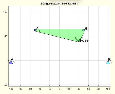 | % fourBarplotPoints(A0,B0,A1,B1,P); - just plot a specific fourbar configuration based on points % (by Tim Lueth, VLFL-Lib, 2021-DEZ-05 as class: KINEMATICS AND FRAMES) % % Introduced first in SolidGeometry 5.1 % % See also: CPLofA1B1P, PosefourbarCPLE % % h=fourBarplotPoints([A0,B0,A1,B1,P]); % === INPUT PARAMETERS === % A0: A0 or CPL with ORDER [A0; B0; B1; A1] % B0: Base of swing % A1: End of Crank % B1: End of Swing % P: Position or Frame of Pose % === OUTPUT RESULTS ====== % h: handle to go % % EXAMPLE: SGfigure; fourBarplotPoints([0 0],[100 0],[0 60],[100 70]) % based on points % SGfigure; fourBarplotPoints([0 0],[100 0],[0 60],[100 70],[40 40]) % including pose % SGfigure; fourBarplotPoints([0 0],[100 0],[0 60],[100 70],TofR(rot(pi/4),[40 40])) % SGfigure; fourBarplotPoints(CPLfourbarcontour ([200,80,100,80]),'','','',[40 40]); % SGfigure; fourBarplotPoints(CPLfourbarcontour ([200,80,100,80]),'','','',TofR(rot(pi/4),[40 40])); % % See also: CPLofA1B1P, PosefourbarCPLE % % % Copyright 2021 Tim C. Lueth |
CPLofA1B1P(A1,B1,P0,R12o,CPLN)- returns a CPL exactly for the given three points |
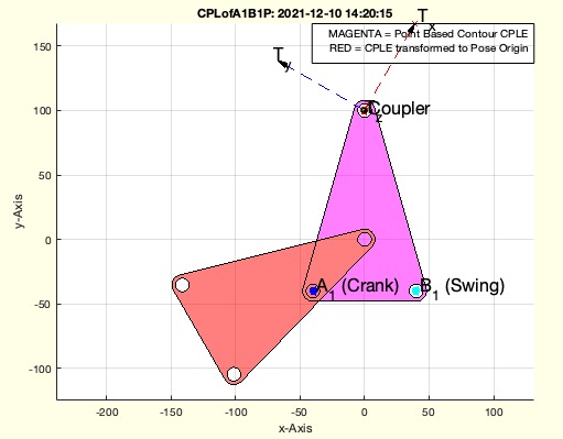 | % CPLofA1B1P(A1,B1,P0,R12o,CPLN) - returns a CPL exactly for the given three points % (by Tim Lueth, VLFL-Lib, 2021-DEZ-05 as class: KINEMATICS AND FRAMES) % % just another (Status of: 2021-12-13) % % Introduced first in SolidGeometry 5.1 % % See also: PosefourbarCPLE, attachmentpointsofA1B1TP, TofA1B1GPL % % [CPLE,T,CPLX]=CPLofA1B1P([A1,B1,P0,R12o,CPLN]) % === INPUT PARAMETERS === % A1: Position of A1 % B1: Position of B1 % P0: 1) Position of Pose or 2) Frame of Pose wen A1 B1 is reached % R12o: Outer and inner Radius for linkages % CPLN: CPLE as additional contour; 0 for an automatic shaped % === OUTPUT RESULTS ====== % CPLE: CPLE % T: Frame of Pose at % CPLX: CPLE at Position T % % EXAMPLE: % CPLofA1B1P([30 0; 0 40; 0 0]); % CPLofA1B1P([30 0], [0 40], [0 0]); % CPLofA1B1P([30 0], [0 40], TofR(rot(pi/4),[0 0])); % CPLofA1B1P([30 0], [0 40], TofR(rot(pi/4),[40 40])); % CPLofA1B1P([30 0], [0 40], TofR(rot(pi/4),[40 40]),'',PLgearDIN(2)); % Add a gear % CPLofA1B1P([30 0], [0 40], TofR(rot(pi/4),[40 40]),'',0); % Add a small L % % % See also: PosefourbarCPLE, attachmentpointsofA1B1TP, TofA1B1GPL % % % Copyright 2021 Tim C. Lueth |
B1ofA1(A1,L2,w)- returns a second attachment point from a 1st Attachment point, distance and angle |
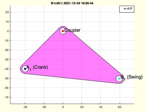 | % B1ofA1(A1,L2,w) - returns a second attachment point from a 1st Attachment point, distance and angle % (by Tim Lueth, VLFL-Lib, 2021-DEZ-04 as class: KINEMATICS AND FRAMES) % % Introduced first in SolidGeometry 5.1 % % See also: KDWofXY, KDWofPoseattachments, PosefourbarCPLE, % TofPoseattachmentpoints, KDWPoseinsideCPL, KDWPosevariation % % B1=B1ofA1(A1,L2,[w]) % === INPUT PARAMETERS === % A1: Attachment Point 1 relative to Origin/Pose center % L2: Length of coupler % w: angle of Pose to achieve % === OUTPUT RESULTS ====== % B1: Position of Attachment Point 2 % % EXAMPLE: % B1ofA1([-40 -40],100) % A1=[-40 -40]; B1ofA1(A1,100,pi/30); B1=ans; % KDWofXY(A1,B1); % [K,D,W]=KDWofXY(A1,B1) % % See also: KDWofXY, KDWofPoseattachments, PosefourbarCPLE, % TofPoseattachmentpoints, KDWPoseinsideCPL, KDWPosevariation % % % Copyright 2021 Tim C. Lueth |
PLofFourbarcouplercurve(A0,B0,A1,B1,GPLA,GPLB,wsol,CPLE)- Creates the coupler courve for an Fourbar given by four points |
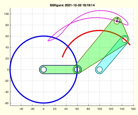 | % PLofFourbarcouplercurve(A0,B0,A1,B1,GPLA,GPLB,wsol,CPLE) - Creates the coupler courve for an Fourbar given by four points % (by Tim Lueth, VLFL-Lib, 2021-DEZ-02 as class: KINEMATICS AND FRAMES) % % This fnctn has an educational code (Status of: 2021-12-02) % % Introduced first in SolidGeometry 5.1 % % See also: PLofPosecouplercurve, PLofPosecentrodes % % [PL0,TL0,wlim,PLC,PLS]=PLofFourbarcouplercurve(A0,B0,A1,B1,[GPLA,GPLB,w % sol,CPLE]) % === INPUT PARAMETERS === % A0: Postion of base point crank % B0: Postion of base point swing % A1: Endpoint of crank % B1: Endpoint of swing % GPLA: optional attachment point of crank at coupler % GPLB: optional attachment point of swing at coupler % wsol: optional angle limitations % CPLE: PLots CPLE in interactive mode % === OUTPUT RESULTS ====== % PL0: Point list of coupler courve % TL0: Frames if coupler courve % wlim: angle limitation =s % PLC: Point list of radial crank movement % PLS: Point list of radial swing movement % % EXAMPLE: % SGfigure; % cla; PLofFourbarcouplercurve([0 0],[100 0],[0 60],[100 +70]); % Plot without attachment points % cla; PLofFourbarcouplercurve([0 0],[100 0],[0 60],[100 -70]); % Plot without attachment points % cla; PLofFourbarcouplercurve([0 0],[100 0],[0 60],[100 70],[-50 -20],[50 0]); % attachment points % cla; PLofFourbarcouplercurve([0 0],[100 0],[0 60],[100 70],[-50 -100],[50 0]); % attachment points % % % See also: PLofPosecouplercurve, PLofPosecentrodes % % % Copyright 2021 Tim C. Lueth |
PosefourbarCPLE(PS,csi,R12o,orig)- creates a CPL for an Effektor containt 3 Points |
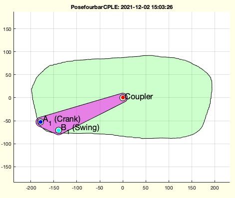 | % PosefourbarCPLE(PS,csi,R12o,orig) - creates a CPL for an Effektor containt 3 Points % (by Tim Lueth, VLFL-Lib, 2021-DEZ-02 as class: KINEMATICS AND FRAMES) % % Better Name CPLofPosefourbarGPL % (Status of: 2021-12-04) % % Introduced first in SolidGeometry 5.1 % % See also: CPLofPoseffector, CPLofPosefourbarshape, % CPLofPosefourbarshaping, B1ofA1 % % [CPLE,PL,T]=PosefourbarCPLE(PS,[csi,R12o,orig]) % === INPUT PARAMETERS === % PS: Pose struct or A1 of GPL % csi: [crank-index swing-index] of GLP for A1 and B1 or B1 of GPL % R12o: [Outradius Innerradius] % orig: '0','A','B' to define the origin; default is '0' % === OUTPUT RESULTS ====== % CPLE: Minimal Effektor contour containing Coupler Pose center % PL: [P0;A1;B1] % T: T to transform the coupler into the origin; default is eye(3) % % EXAMPLE: % PosereadAPD('/Volumes/LUETH-WIN/MATLAB_files_for_experiments/basecabinet_new.APD');PS=ans; % PS.CPLE=CPLfillinside(PS.CPLE); % PosefourbarCPLE(PS,[1 15],10) % CALLED WITH INDEX CI and SI in GPL % PosefourbarCPLE([10 10],[20 10]) % CALLED WITH A1 and B1 of Coupler % % See also: CPLofPoseffector, CPLofPosefourbarshape, % CPLofPosefourbarshaping, B1ofA1 % % % Copyright 2021 Tim C. Lueth |
strfindtag(txt,srch,endstr,endnl)- returns a string after a search string |
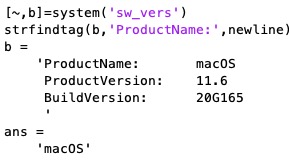 | % strfindtag(txt,srch,endstr,endnl) - returns a string after a search string % (by Tim Lueth, VLFL-Lib, 2021-DEZ-02 as class: AUXILIARY PROCEDURES) % % Introduced first in SolidGeometry 5.1 % % See also: strfindafter, SGfindswitchcaseconditions, strrepn, strrepalias % % nam=strfindtag(txt,srch,[endstr,endnl]) % === INPUT PARAMETERS === % txt: text % srch: search string % endstr: end tag to % endnl: optional new line % === OUTPUT RESULTS ====== % nam: trimmed name tag % % EXAMPLE: % [~,b]=system('sw_vers') % strfindtag(b,'ProductName:',newline) % % % See also: strfindafter, SGfindswitchcaseconditions, strrepn, strrepalias % % % Copyright 2021-2022 Tim C. Lueth |
verOSX- just tired to find out why and when matlab chashes |
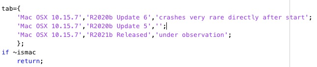 | % verOSX - just tired to find out why and when matlab chashes % (by Tim Lueth, VLFL-Lib, 2021-DEZ-02 as class: AUXILIARY PROCEDURES) % % Introduced first in SolidGeometry 5.1 % % See also: verTL, ver, isatleastVer, iscalledbycmdline % % [osx,mlw]=verOSX % === OUTPUT RESULTS ====== % osx: osx version % mlw: warning on matlab stability % % EXAMPLE: % verOSX; % [a,b]=verOSX % % % See also: verTL, ver, isatleastVer, iscalledbycmdline % % % Copyright 2021 Tim C. Lueth |
BBofBB(ax,d)- scales an axis our bounding box |
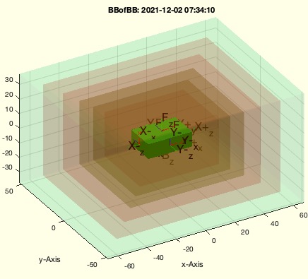 | % BBofBB(ax,d) - scales an axis our bounding box % (by Tim Lueth, VLFL-Lib, 2021-DEZ-02 as class: VISUALIZATION) % % if abs(d) > 1 then d consists of absolute values % if abs(d) < 1 then d consists of relative values % (Status of: 2021-12-02) % % Introduced first in SolidGeometry 5.1 % % See also: BBofCPL, BBofCPS, BBofPose, BBofPS, BBofSG, BBofT, BBofVL, % BBofSGcutT % % nx=BBofBB([ax,d]) % === INPUT PARAMETERS === % ax: Bounding box % d: scaling vector % === OUTPUT RESULTS ====== % nx: new exis % % EXAMPLE: % SGbox;ax=BBofBB(axis,0.1); axis(ax) % BBofBB('',0.1); % % See also: BBofCPL, BBofCPS, BBofPose, BBofPS, BBofSG, BBofT, BBofVL, % BBofSGcutT % % % Copyright 2021 Tim C. Lueth |
CPLcrosslineauxpoints(CPL,p1,p2,md)- creates crossing points of a line a a contour with a grid size |
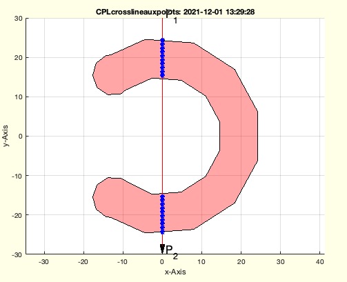 | % CPLcrosslineauxpoints(CPL,p1,p2,md) - creates crossing points of a line a a contour with a grid size % (by Tim Lueth, VLFL-Lib, 2021-DEZ-01 as class: CLOSED POLYGON LISTS) % % will be improved in future. Fnctn is used to create base points for % mechanisms design along of straigt lines within a defined contour % (Status of: 2021-12-24) % % Introduced first in SolidGeometry 5.1 % % See also: crossC2P, CPLofPLcrossCPL % % GPL=CPLcrosslineauxpoints(CPL,p1,p2,md) % === INPUT PARAMETERS === % CPL: Contour % p1: Start Point % p2: End Point % md: distance; default is 1mm % === OUTPUT RESULTS ====== % GPL: Gridpointlist % % EXAMPLE: % CPLcrosslineauxpoints(CPLsample(18),[0 -30],[0 +30],5) % % % See also: crossC2P, CPLofPLcrossCPL % % % Copyright 2021 Tim C. Lueth |
exp_2021_12_01_Pose2synth- shows how to perform a 3 Pose Fourbar syntheses and a 2 Pose Fourbar syntheses and |
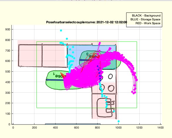 | % exp_2021_12_01_Pose2synth - shows how to perform a 3 Pose Fourbar syntheses and a 2 Pose Fourbar syntheses and % (by Tim Lueth, VLFL-Lib, 2021-DEZ-01 as class: EXPERIMENTS) % % Introduced first in SolidGeometry 5.1 % % exp_2021_12_01_Pose2synth % % EXAMPLE: % exp_2021_12_01_Pose2synth % % % Copyright 2021 Tim C. Lueth |
checkfourbar2Poseattachpermutation(PS,psel,m)- Returns solutions for the 2 Pose Sythesis |
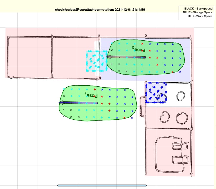 | % checkfourbar2Poseattachpermutation(PS,psel,m) - Returns solutions for the 2 Pose Sythesis % (by Tim Lueth, VLFL-Lib, 2021-DEZ-01 as class: KINEMATICS AND FRAMES) % % The 3 poses synthesis searches for frame points and attachment points % on an effector so that it can perform a certain movement. It is % possible that one of the three poses was selected in an unsatisfactory % way, so that the frame points are not located in the desired area. A % manual shift and visualization of the effect is given with the % Posetransui fnctn. This fnctn Posetrans4basepos is an attempt to fix % two poses and analyze where the third pose would be and whether the % solution is acceptable, based on the desired frame point positions. % (Status of: 2021-12-08) % % Introduced first in SolidGeometry 5.1 % % See also: isincirclesegment, Posetransui, % checkfourbar3Poseattachpermutation, checkfourbar1Poseattachpermutation, % Posefourbarplotcouplercurve % % PS=checkfourbar2Poseattachpermutation(PS,[psel,m]) % === INPUT PARAMETERS === % PS: Pose struct % psel: Selection of poses to fix; typically the end poses % m: [GridNr distlink dist base] % === OUTPUT RESULTS ====== % PS: Pos including field 'solut' % % EXAMPLE: % fname=loadweb('Posebasecabinet.APD'); PS=PosereadAPD(fname); % PosereadAPD('/Volumes/LUETH-WIN/MATLAB_files_for_experiments/basecabinet_new.APD');PS=ans; % PS=checkfourbar3Poseattachpermutation(PS) % PS=Posetransui(PS) % checkfourbar2Poseattachpermutation(PS,[1 3]); PS=ans; % % See also: isincirclesegment, Posetransui, % checkfourbar3Poseattachpermutation, checkfourbar1Poseattachpermutation, % Posefourbarplotcouplercurve % % % Copyright 2021-2022 Tim C. Lueth |
VMofimagestack(imnam,r90,scl,angle)- performs the inverse radon on an image stack |
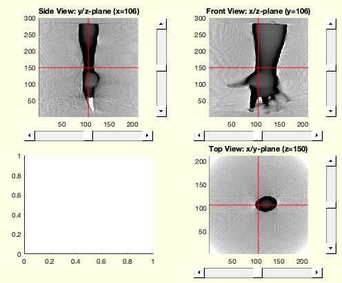 | % VMofimagestack(imnam,r90,scl,angle) - performs the inverse radon on an image stack % (by Tim Lueth & Valentin Ameres, VLFL-Lib, 2021-NOV-29 as class: VOXELS) % % Introduced first in SolidGeometry 5.1 % % See also: imstackread, imstackwrite, imstackofSGprojection, % VMof2Dprojections % % VM=VMofimagestack([imnam,r90,scl,angle]) % === INPUT PARAMETERS === % imnam: image matrix or folder name (File name) % r90: rotate the image minus 90 degree; default is true % scl: scale the image; default is 1 % angle: default i 360 % === OUTPUT RESULTS ====== % VM: Voxel Model % % EXAMPLE: % IS=imstackread; % VM=VMofimagestack(IS); % SGofVMisosurface(VM<115) % % % See also: imstackread, imstackwrite, imstackofSGprojection, % VMof2Dprojections % % % Copyright 2021 Tim C. Lueth |
imstackread(dirname,r90,siz,scl,"ext")- reads in an image stack as default uint16 |
 | % imstackread(dirname,r90,siz,scl,"ext") - reads in an image stack as default uint16 % (by Tim Lueth & Valentin Ameres, VLFL-Lib, 2021-NOV-29 as class: IMAGES) % % Introduced first in SolidGeometry 5.1 % % See also: imstackofSGprojection, imstackwrite, VMofimagestack % % [IS,seldir]=imstackread([dirname,r90,siz,scl,"ext"]) % === INPUT PARAMETERS === % dirname: folder name or file name % r90: if true, imageas are rotated; default is TRUE % siz: size; default is taken from file size % scl: scaling; default is 1 % "ext": default is 'raw' % === OUTPUT RESULTS ====== % IS: image stack % seldir: selected directory % % EXAMPLE: % imstackofSGprojection(SGsample(17)); IS=ans; % CREATE PROJECTION IMAGES 300x300 % imstackwrite(IS,'test'); dname=ans; % WRITE RAW FILE DIRECTORY % imstackread(dname,false,'',2); IS=ans; % READIN STACK % % See also: imstackofSGprojection, imstackwrite, VMofimagestack % % % Copyright 2021-2022 Tim C. Lueth |
imstackwrite(IS,dirnam,spr,inv)- writes a gray scale intesity matrix n x n x m into raw files (used for radon) |
 | % imstackwrite(IS,dirnam,spr,inv) - writes a gray scale intesity matrix n x n x m into raw files (used for radon) % (by Tim Lueth, VLFL-Lib, 2021-NOV-28 as class: IMAGES) % % currently the format is uint 16 raw and the intensity is streched from % 08 to to 12 bit (Status of: 2021-11-29) % % Introduced first in SolidGeometry 5.1 % % See also: imstackofSGprojection, imstackread % % dirnam=imstackwrite([IS,dirnam,spr,inv]) % === INPUT PARAMETERS === % IS: Image stack (n x n x m) % dirnam: directory name % spr: if true; the images are spreaded to achieve maximum of intensity; % default is false % inv: if true; the images are inverted change b/w to w/b; default is % false % === OUTPUT RESULTS ====== % dirnam: name of directory created % % EXAMPLE: % loadweb JACO_robot.mat % imstackofSGprojection(SGtrans0(JC1)); IS=ans; % fname=imstackwrite(IS) % % % See also: imstackofSGprojection, imstackread % % % Copyright 2021 Tim C. Lueth |
imadjustwhite(IS)- adjusts the intensity values from both side that |
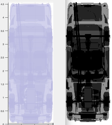 | % imadjustwhite(IS) - adjusts the intensity values from both side that % (by Tim Lueth, VLFL-Lib, 2021-NOV-27 as class: IMAGES) % % 99.8% of the values define the spread % This fnctn is used to create pseudo CT images from a figure projections % (Status of: 2021-11-29) % % Introduced first in SolidGeometry 5.1 % % See also: spreadmax % % IS=imadjustwhite(IS) % === INPUT PARAMETERS === % IS: original intensity matrix % === OUTPUT RESULTS ====== % IS: modified intensity matrix % % See also: spreadmax % % % Copyright 2021 Tim C. Lueth |
spreadmax(IS,mm)- spreads the values of a matrix for a desired intervall min to max |
 | % spreadmax(IS,mm) - spreads the values of a matrix for a desired intervall min to max % (by Tim Lueth, VLFL-Lib, 2021-NOV-27 as class: IMAGES) % % used in imstackofSGprojection % (Status of: 2021-11-29) % % Introduced first in SolidGeometry 5.1 % % See also: imadjustwhite, imstackofSGprojection % % ISN=spreadmax(IS,[mm]) % === INPUT PARAMETERS === % IS: matrix % mm: [min max]; defualt is [0 255] % === OUTPUT RESULTS ====== % ISN: new matrix % % See also: imadjustwhite, imstackofSGprojection % % % Copyright 2021 Tim C. Lueth |
exp_2021_11_26_Holefix(incr)- Experiment to prove that holes/contours with different wall thicknesses can be sliced |
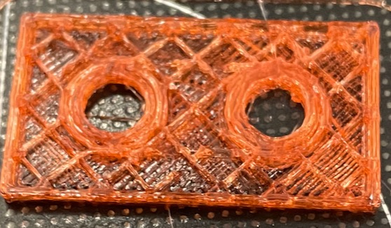 | % exp_2021_11_26_Holefix(incr) - Experiment to prove that holes/contours with different wall thicknesses can be sliced % (by Tim Lueth, VLFL-Lib, 2021-NOV-26 as class: EXPERIMENTS) % % Based on an idea originally by Erik Löwe from 2008 for coloring the % z-corp printed colored solids % The experiment shows that even the slices to set to 0.8 mm wall % thickness, it is possible to have sliceed and 3d printed solids whose % drilling holes have a wall thickness if 1.8mm. % Fnctn writes a file "HOLEFIX.STL" to used with Ultimaker CURA Sclicer % and wall thickness 0.8 and infill % (Status of: 2021-11-26) % % Introduced first in SolidGeometry 5.1 % % exp_2021_11_26_Holefix([incr]) % === INPUT PARAMETERS === % incr: if true; the wall is increased by 1 mm; default is true; % % % Copyright 2021 Tim C. Lueth |
VofRsphere(R,M)- Lead or steel balls must be installed in cavities to create ballast |
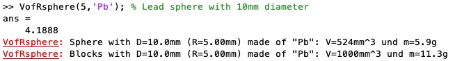 | % VofRsphere(R,M) - Lead or steel balls must be installed in cavities to create ballast % (by Tim Lueth, VLFL-Lib, 2021-NOV-26 as class: AUXILIARY PROCEDURES) % % Introduced first in SolidGeometry 5.1 % % See also: V2A % % [V,W,M]=VofRsphere([R,M]) % === INPUT PARAMETERS === % R: Radius [r h]; default is [r r] % M: Material such as 'Fe', 'Pb', 'Si' % === OUTPUT RESULTS ====== % V: Volume % W: Weight % M: Material % % EXAMPLE: % VofRsphere(5,'Pb'); % Lead sphere with 10mm diameter % % See also: V2A % % % Copyright 2021 Tim C. Lueth |
CPLfeatureedge(CPL,al)- selects corners with an angle larger a limit |
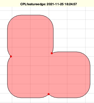 | % CPLfeatureedge(CPL,al) - selects corners with an angle larger a limit % (by Tim Lueth, VLFL-Lib, 2021-NOV-25 as class: CLOSED POLYGON LISTS) % % Introduced first in SolidGeometry 5.1 % % See also: PLangle, PLELofFeatureEdges % % [FE,FEi]=CPLfeatureedge(CPL,[al]) % === INPUT PARAMETERS === % CPL: Closed Polygon list % al: alpha; default is pi/4 (45 degree) % === OUTPUT RESULTS ====== % FE: List of Points % FEi: Index of FE within CPL % % EXAMPLE: % CPLfeatureedge(CPLsample(1)) % random shape % CPLfeatureedge(PLcircle(1)) % 16 edges, limit is 16 % CPLfeatureedge(PLcircle(2)) % 32 edges but limit to small % % See also: PLangle, PLELofFeatureEdges % % % Copyright 2021 Tim C. Lueth |
celltype(C,tppe)- creates any type check for cells - Missing matlab fnct or at least unknown to me |
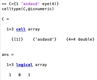 | % celltype(C,tppe) - creates any type check for cells - Missing matlab fnct or at least unknown to me % (by Tim Lueth, VLFL-Lib, 2021-NOV-25 as class: AUXILIARY PROCEDURES) % % Some matlab fnctn such as startsWith work with cell list bu fail if the % type of the cell elements does not fit. Therefor there is a need to % check only the elements that fit % % (Status of: 2021-11-25) % % Introduced first in SolidGeometry 5.1 % % See also: startsWith, ismemberincell % % celltype(C,tppe) % === INPUT PARAMETERS === % C: Cell ist % tppe: type tu check such as @ischar or @isnumeric % % EXAMPLE: % C={1 'asdasd' eye(4)} % celltype(C,@isnumeric) % % See also: startsWith, ismemberincell % % % Copyright 2021 Tim C. Lueth |
CPLfitinCPLrot(CPLA,CPLB,n)- shifts a CPL into the center of another and rotates for optimal fit |
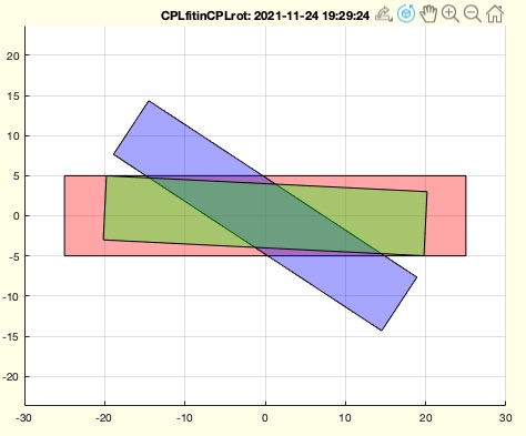 | % CPLfitinCPLrot(CPLA,CPLB,n) - shifts a CPL into the center of another and rotates for optimal fit % (by Tim Lueth, VLFL-Lib, 2021-NOV-23 as class: CLOSED POLYGON LISTS) % % Introduced first in SolidGeometry 5.1 % % See also: CPLfitinCPLscale, CPLfitsinCPL % % [CPLN,ww]=CPLfitinCPLrot(CPLA,CPLB,[n]) % === INPUT PARAMETERS === % CPLA: CPL to fit CPLB in % CPLB: CPL to be rotated to fit into CPLA % n: number of angeles to try for best fit; default is % === OUTPUT RESULTS ====== % CPLN: New Conotur % ww: rotation angle % % EXAMPLE: % CPLfitinCPLrot(PLsquare([50,10]), 30+PLtransR(PLsquare([40,8]),rot(pi*rand)),40) % % See also: CPLfitinCPLscale, CPLfitsinCPL % % % Copyright 2021 Tim C. Lueth |
CPLfitinCPLscale(CPLA,CPLB,bs)- Scales and moves contour to fit into another |
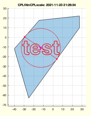 | % CPLfitinCPLscale(CPLA,CPLB,bs) - Scales and moves contour to fit into another % (by Tim Lueth, VLFL-Lib, 2021-NOV-23 as class: CLOSED POLYGON LISTS) % % Introduced first in SolidGeometry 5.1 % % See also: CPLfitinCPLrot % % CPLB=CPLfitinCPLscale(CPLA,CPLB,[bs]) % === INPUT PARAMETERS === % CPLA: Contour to fit in % CPLB: Contour that has to be scaled to fit in CPLA % bs: border size; default is 0 % === OUTPUT RESULTS ====== % CPLB: final scaled contour % % EXAMPLE: % CPLfitinCPLscale(CPLsample(1),CPLtextimage('test',400)) % CPLfitinCPLscale(CPLsample(1),CPLtextimage('test',400),2) % 2mm distance to the walls % % See also: CPLfitinCPLrot % % % Copyright 2021 Tim C. Lueth |
SGreadSTLdir(dirname,mag,fac)- reads all STL files of a folder into one SG cell list |
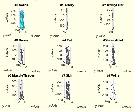 | % SGreadSTLdir(dirname,mag,fac) - reads all STL files of a folder into one SG cell list % (by Tim Lueth, VLFL-Lib, 2021-NOV-19 as class: FILE HANDLING) % % Introduced first in SolidGeometry 5.1 % % See also: SGreadSTL, SGwriteSTL, VLFLreadSTL, VLFLwriteSTL, stldir % % SG=SGreadSTLdir([dirname,mag,fac]) % === INPUT PARAMETERS === % dirname: folder name or single file in a folder % mag: magnification; default is 1 % fac: maximum number of facets overall % === OUTPUT RESULTS ====== % SG: Cell list of Solids % % See also: SGreadSTL, SGwriteSTL, VLFLreadSTL, VLFLwriteSTL, stldir % % % Copyright 2021-2022 Tim C. Lueth |
subplotnumber(fig)- simply returns the number of subplots |
 | % subplotnumber(fig) - simply returns the number of subplots % (by Tim Lueth, VLFL-Lib, 2021-NOV-18 as class: VISUALIZATION) % % Introduced first in SolidGeometry 5.1 % % See also: plotannotation, selectsubplot % % [n,subs]=subplotnumber([fig]) % === INPUT PARAMETERS === % fig: default is gcf % === OUTPUT RESULTS ====== % n: number of subplots % subs: list of handles % % EXAMPLE: % PLsample; subplotnumber % % % See also: plotannotation, selectsubplot % % % Copyright 2021 Tim C. Lueth |
CPLbufferCPLlines(CPL,d)- converts a set of lines into a closed polygon concept |
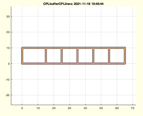 | % CPLbufferCPLlines(CPL,d) - converts a set of lines into a closed polygon concept % (by Tim Lueth, VLFL-Lib, 2021-NOV-18 as class: CLOSED POLYGON LISTS) % % Introduced first in SolidGeometry 5.1 % % See also: CPLofmeshgrid % % CPLN=CPLbufferCPLlines(CPL,d) % === INPUT PARAMETERS === % CPL: CPL consisting of open lines without meshes % d: buffer width % === OUTPUT RESULTS ====== % CPLN: New CPL or CPS % % EXAMPLE: % CPLofmeshgridrods([0 15 25 35 45 55 65],[0 10]); x=ans; % CPLbufferCPLlines(x,1); % CPLbufferCPLlines(PLcircle(10),1); % CPLbufferCPLlines(CPLofPL(PLcircle(10)),1); % % See also: CPLofmeshgrid % % % Copyright 2021 Tim C. Lueth |
imstackofSGprojection(SG,sz,nw,tr)- creates projection images similar to a CT from a solid |
 | % imstackofSGprojection(SG,sz,nw,tr) - creates projection images similar to a CT from a solid % (by Tim Lueth, VLFL-Lib, 2021-NOV-17 as class: IMAGES) % % Introduced first in SolidGeometry 5.1 % % See also: VMof2Dprojections, imstackwrite, imstackread % % IS=imstackofSGprojection([SG,sz,nw,tr]) % === INPUT PARAMETERS === % SG: Solid Geometry; default is SGofgca % sz: size; default is 300 % nw: number of images; default is 180 % tr: transparency level; default is 0.4 % === OUTPUT RESULTS ====== % IS: image stack % % EXAMPLE: % SGloadAdamEva; SG=ans; % % See also: VMof2Dprojections, imstackwrite, imstackread % % % Copyright 2021 Tim C. Lueth |
VMcaxis2(VM,sect)- adjustes the caxis of the VMplot diagram |
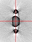 | % VMcaxis2(VM,sect) - adjustes the caxis of the VMplot diagram % (by Tim Lueth, VLFL-Lib, 2021-NOV-17 as class: VOXELS) % % In contrast to VMcaxis, which look for minmaxall(VM), this fnctn % VMcaxis2 uses the intenstity area to cover 98% of the image histogram % intensities % SLOW fnctn (Status of: 2021-11-17) % % Introduced first in SolidGeometry 5.1 % % See also: VMplot, VMwindowplot, VMcaxis, histograms % % ca=VMcaxis2(VM,[sect]) % === INPUT PARAMETERS === % VM: [cmin cmax]; default is min and max of the current! surfaces % sect: number of sections for the histogramm; default is 64 % === OUTPUT RESULTS ====== % ca: selected Values if called without input paramter % % EXAMPLE: % VMplot(VM) % VMcaxis2 % % See also: VMplot, VMwindowplot, VMcaxis, histograms % % % Copyright 2021 Tim C. Lueth |
SGBAUHAUSbox(siz,b,cutw)- designs a BAUHAUS style boxes to hide cables and stuff |
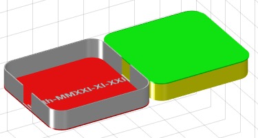 | % SGBAUHAUSbox(siz,b,cutw) - designs a BAUHAUS style boxes to hide cables and stuff % (by Tim Lueth, VLFL-Lib, 2021-NOV-17 as class: MODELING PROCEDURES) % % This is an homage to the BAUHAUS idea of 1920 to design simple % geometries in colors that fulfil a task in daily life. Fnctn writes ans % STL to computer desktop dir % x y z are dimensions of box % r radius % w wall thickness % l = height of inner cover (Status of: 2021-11-21) % % Introduced first in SolidGeometry 5.1 % % See also: SGcompass, SGboxMacmini, SGBAUHAUSdeskcylinder % % [box,cov]=SGBAUHAUSbox([siz,b,cutw]) % === INPUT PARAMETERS === % siz: [x y z r w l]; default is [160 25 20 2] % b: width of opening; default is z/2 % cutw: angles for openings; default is [0, pi] % === OUTPUT RESULTS ====== % box: SG of box % cov: SG of cover % % EXAMPLE: % SGBAUHAUSbox([30 20 10 2 1 5]) % SGBAUHAUSbox([195,195,36,2,2,1]) % MAC mini shpaed Box % SGBAUHAUSbox([150 54 65 1 2 0],0) % Box for sun glasses % % See also: SGcompass, SGboxMacmini, SGBAUHAUSdeskcylinder % % % Copyright 2021 Tim C. Lueth |
CPLtextbanner(txt,sz,r,rem)- Returs a CPL for an size adjusted Textbanner or Contour |
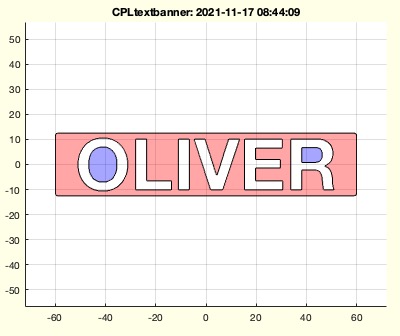 | % CPLtextbanner(txt,sz,r,rem) - Returs a CPL for an size adjusted Textbanner or Contour % (by Tim Lueth, VLFL-Lib, 2021-NOV-17 as class: CLOSED POLYGON LISTS) % % extracted from SGtextbanner % if border==0; the border is calculated automatically (Status of: % 2021-11-17) % % Introduced first in SolidGeometry 5.1 % % See also: SGtextstamp, SGtextbanner % % [CPL,CPLT,CPLB]=CPLtextbanner([txt,sz,r,rem]) % === INPUT PARAMETERS === % txt: Text or CPL to enclose % sz: [widht height border]; default is [120 25 4]; % r: optional radius; default is automatic border/2 % rem: if true; the contours that would fall out are removed; default % === OUTPUT RESULTS ====== % CPL: of Text Banner % CPLT: CPL of Text contour % CPLB: CPL of Box Contour % % EXAMPLE: % CPLtextbanner % CPLtextbanner('DISZIPLIN') % CPLtextbanner(PLcircle([10 20 30 40]),[40 20]) % % See also: SGtextstamp, SGtextbanner % % % Copyright 2021 Tim C. Lueth |
SGtextbanner(txt,sz,r)- Returs a solid an a CPL for an size adjusted Textbanner |
 | % SGtextbanner(txt,sz,r) - Returs a solid an a CPL for an size adjusted Textbanner % (by Tim Lueth, VLFL-Lib, 2021-NOV-15 as class: MODELING PROCEDURES) % % Introduced first in SolidGeometry 5.1 % % See also: SGtextstamp % % [SG,CPL,CPLT,CPLB]=SGtextbanner([txt,sz,r]) % === INPUT PARAMETERS === % txt: Text % sz: [widht height border thickness]; default is 120 25 5 2] % r: optional radius; default is automatic % === OUTPUT RESULTS ====== % SG: SG % CPL: SG contour % CPLT: Text contour % CPLB: Box Contour % % EXAMPLE: % SGtextbanner('DISZIPLIN') % % See also: SGtextstamp % % % Copyright 2021 Tim C. Lueth |
SGBAUHAUSdeskcylinder(siz,num,cutw)- designs a BAUHAUS style boxes to hide cables and stuff |
 | % SGBAUHAUSdeskcylinder(siz,num,cutw) - designs a BAUHAUS style boxes to hide cables and stuff % (by Tim Lueth, VLFL-Lib, 2021-NOV-13 as class: MODELING PROCEDURES) % % This is an homage to the BAUHAUS idea of 1920 to design simple % geometries in colors that fulfil a task in daily life % % writes an STL to the computer desktop folder (Status of: 2021-11-21) % % Introduced first in SolidGeometry 5.1 % % See also: SGcompass, SGboxMacmini, SGBAUHAUSbox % % [box,cov]=SGBAUHAUSdeskcylinder([siz,num,cutw]) % === INPUT PARAMETERS === % siz: [diameter height height wall slot]; default is [160 30 2 2 0] % num: number of edges; default is []; % cutw: angles for openings; default is [0, -pi/5, +pi/5] % === OUTPUT RESULTS ====== % box: SG of box % cov: SG of cover % % EXAMPLE: % SGBAUHAUSdeskcylinder([160 25 20 2 40]) % SGBAUHAUSdeskcylinder([160 25 20 2 40],6,[0 , -pi/2]) % 6 Edges, 90 degree holes % % See also: SGcompass, SGboxMacmini, SGBAUHAUSbox % % % Copyright 2021 Tim C. Lueth |
SGboxMacmini- designs a cylinder shaped box for my office desk to hide cables and stuff |
 | % SGboxMacmini - designs a cylinder shaped box for my office desk to hide cables and stuff % (by Tim Lueth, VLFL-Lib, 2021-NOV-11 as class: MODELING PROCEDURES) % % This is an homage to the BAUHAUS idea of 1920 to design simple % geometries in colors that fulfil a task in daily life % % writes ans STL to computer desktop dir (Status of: 2021-11-13) % % Introduced first in SolidGeometry 5.1 % % See also: SGcompass % % [box,cov]=SGboxMacmini % === OUTPUT RESULTS ====== % box: SG of the box % cov: SG of the cover % % EXAMPLE: Just call: % % SGboxMacmini % % See also: SGcompass % % % Copyright 2021 Tim C. Lueth |
SGcutrecursivly(SG,lim)- cuts a part recursively into pieces until it fits a maximum dimensions |
 | % SGcutrecursivly(SG,lim) - cuts a part recursively into pieces until it fits a maximum dimensions % (by Tim Lueth, VLFL-Lib, 2021-NOV-11 as class: SURFACES) % % Useful to separate parts into pices without positive locking % The cut is done in order of the largest need/ratio for shortening % (Status of: 2021-11-11) % % Introduced first in SolidGeometry 5.1 % % See also: SGpuzzlecut3D % % SG=SGcutrecursivly(SG,[lim]) % === INPUT PARAMETERS === % SG: Solid Geometry % lim: cutting dimensions; default is [inf inf inf] % === OUTPUT RESULTS ====== % SG: Cell list of Solid Geometries % % EXAMPLE: % SGcutrecursivly(SGboxMarie,10) % SGcutrecursivly(SGofCPLz(PLtriangle('','',40),10),[100 10 ]) % % % See also: SGpuzzlecut3D % % % Copyright 2021 Tim C. Lueth |
imreadraw(filname,sz,bit)- reads an image file as raw data |
 | % imreadraw(filname,sz,bit) - reads an image file as raw data % (by Tim Lueth & Valentin Ameres, VLFL-Lib, 2021-NOV-04 as class: IMAGES) % % Introduced first in SolidGeometry 5.1 % % See also: imread, imreadui, imreadlastchanged, imreadraw % % % [IMG,sz]=imreadraw([filname,sz,bit]) % === INPUT PARAMETERS === % filname: raw data projection image file % sz: rows and cols of the image;default is automatic detection of a % square matrix % bit: bits per pixel; default is 16 % === OUTPUT RESULTS ====== % IMG: single image as real matrix % sz: size or detected size % % EXAMPLE: % imreadraw('/Volumes/LUETH-WIN/WIN AIM Matlab Libraries/2D_Xray_Projection_(Ameres)/raw_2016_07_13/_0368,00_0031.raw') % % See also: imread, imreadui, imreadlastchanged, imreadraw % % % % Copyright 2021 Tim C. Lueth |
VMof2Dprojections(dirname,angle,siz,lim,scl,r90)- this fnct reads in a directory full of projection images and creates a voxel model |
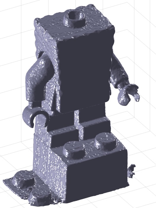 | % VMof2Dprojections(dirname,angle,siz,lim,scl,r90) - this fnct reads in a directory full of projection images and creates a voxel model % (by Tim Lueth & Valentin Ameres, VLFL-Lib, 2021-NOV-04 as class: VOXELS) % % This fnctn creates automatically a directory within the given directory % to story the reconstrion include date and time (Status of: 2021-11-17) % % Introduced first in SolidGeometry 5.1 % % See also: VMofSG, VMofSGweight % % [VM,SG,IMG]=VMof2Dprojections([dirname,angle,siz,lim,scl,r90]) % === INPUT PARAMETERS === % dirname: directory name or file name; default is empty => manual select % angle: angle list or maximum area value of the projection images; % default is 360 % siz: size of the images; default is squared image matrix % lim: limit; default is '' == automatic % scl: scaling; default is 1 % r90: rotate the images 90 degree; default is true % === OUTPUT RESULTS ====== % VM: Voxel model % SG: Surface Model % IMG: Image Stack % % EXAMPLE: % '/Volumes/LUETH-WIN/WIN AIM Matlab Libraries/2D_Xray_Projection_(Ameres)/raw_2016_07_13/_0368,00_0031.raw') % % % See also: VMofSG, VMofSGweight % % % Copyright 2021 Tim C. Lueth |
stldir(fname)- returns path, or filename, or list of existing files |
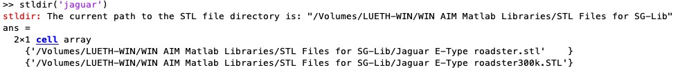 | % stldir(fname) - returns path, or filename, or list of existing files % (by Tim Lueth, VLFL-Lib, 2021-NOV-04 as class: FILE HANDLING) % % ATTENTION - non conform argout % This fnctn is a mixture of pathname, adding a pathname, and finding % files similar to which written especially for STL files, but could % easyl modified for alls extensions (Status of: 2021-11-04) % % Introduced first in SolidGeometry 5.1 % % See also: desktopdir % % [flist,fdir]=stldir([fname]) % === INPUT PARAMETERS === % fname: strinf to search for in the stl default directory % === OUTPUT RESULTS ====== % flist: stldir or path to stldir or list of all files that contains the % search string % fdir: corresponding dir result % % EXAMPLE: % [stldir filesep 'sdsd'] % just returns stldir as string % stldir('sdsd') % creates a new filename in to stldir % stldir('jaguar') % fnds all files that contain the string jaguar % % % See also: desktopdir % % % Copyright 2021 Tim C. Lueth |
SGfigureInteractiveMove(SGfigureInteractiveMovebutton)- Interactive moving of patches on the screen |
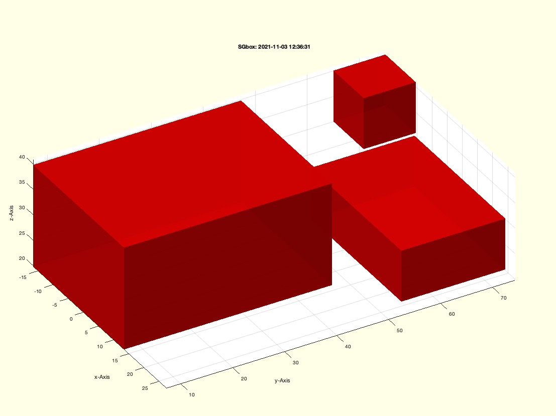 | % SGfigureInteractiveMove(SGfigureInteractiveMovebutton) - Interactive moving of patches on the screen % (by Tim Lueth, VLFL-Lib, 2021-NOV-03 as class: USER INTERFACE) % % 0 = do nothing % 1 = 'left' click % 2 = 'right' click % 3 = 'middle' click % 4 = 'double' click (Status of: 2021-11-06) % % Introduced first in SolidGeometry 5.1 % % See also: SGfigureInteractiveSort % % SGfigureInteractiveMove([SGfigureInteractiveMovebutton]) % === INPUT PARAMETERS === % SGfigureInteractiveMovebutton: Task Order 'VIEW ROTATION' 'SOLID MOVE' % 'Solid Rotate'; default is [2 1 3] % % EXAMPLE: % SGloadAdamEva; % SGbox([30 20 10;30 40 20;10 10 10],'','randxy',true); % SGfigureInteractiveMove % Left=move; right = view rotation; middle = rotate % SGfigureInteractiveMove ([2 1 0]) % No surface rotation % % See also: SGfigureInteractiveSort % % % Copyright 2021 Tim C. Lueth |
SGfigureInteractiveSort(SG)- fnct to sort surfaces into two independent solids interactevely |
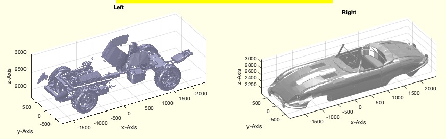 | % SGfigureInteractiveSort(SG) - fnct to sort surfaces into two independent solids interactevely % (by Tim Lueth, VLFL-Lib, 2021-NOV-02 as class: SURFACES) % % Opens two subplots and allos by mouseclick to swap surfaces from a left % or a right window (Status of: 2021-11-03) % % Introduced first in SolidGeometry 5.1 % % See also: SGsurfaces % % [SGR,SGL]=SGfigureInteractiveSort(SG) % === INPUT PARAMETERS === % SG: Original Solid % === OUTPUT RESULTS ====== % SGR: Right selection % SGL: Left selection % % EXAMPLE: % SGreadSTL('../STL Files for SG-Lib/Jaguar E-Type Roadstart 300000.STL'); SG=ans; % SGfigureInteractiveSort(SG); % % % See also: SGsurfaces % % % Copyright 2021 Tim C. Lueth |
SGopentoline(fname,line)- same as opentoline which does not work anymore in 2020b Update6 on Catilina |
 | % SGopentoline(fname,line) - same as opentoline which does not work anymore in 2020b Update6 on Catilina % (by Tim Lueth, VLFL-Lib, 2021-NOV-02 as class: AUXILIARY PROCEDURES) % % simply the same as % matlab.desktop.editor.openAndGoToLine(which(fname),line) (Status of: % 2021-11-02) % % Introduced first in SolidGeometry 5.1 % % See also: opentoline, matlab.desktop.editor.openAndGoToLine % % SGopentoline(fname,line) % === INPUT PARAMETERS === % fname: filename % line: line number % % EXAMPLE: % SGopentoline('PLcircle',20) % % See also: opentoline, matlab.desktop.editor.openAndGoToLine % % % Copyright 2021 Tim C. Lueth |
dbprintmode(md)- switches on the possibility to reach code lines when using dbprintf fnct |
 | % dbprintmode(md) - switches on the possibility to reach code lines when using dbprintf fnct % (by Tim Lueth, VLFL-Lib, 2021-NOV-02 as class: LANGUAGE PROCEDURES) % % A fnctn, MathWorks should implement for quick debugging. Same % fnctnality also implemented for dbreturn. By using dbprintmode, it is % possible to ectivate the openinline fnctn to reach the fnctn call % immedeatly (Status of: 2021-11-02) % % Introduced first in SolidGeometry 5.1 % % See also: dbreturn, dbprintf, dbexit, debugTL, dbsave % % dbmode=dbprintmode([md]) % === INPUT PARAMETERS === % md: true or false; default is true; % === OUTPUT RESULTS ====== % dbmode: true or false % % EXAMPLE: % can be tested only within functns % dbprintf % dbprintmode on % dbprintf % % See also: dbreturn, dbprintf, dbexit, debugTL, dbsave % % % Copyright 2021-2022 Tim C. Lueth |
SGremimprint(SG,fil)- removes engravings on a defined feature surface |
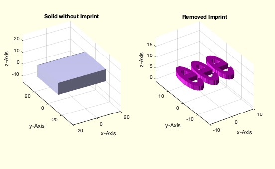 | % SGremimprint(SG,fil) - removes engravings on a defined feature surface % (by Tim Lueth, VLFL-Lib, 2021-OKT-31 as class: SURFACES) % % In many downloaded geometries from the Internet there are engravings in % the surface which appear inappropriate after the modification of the % geometry. These are to be removed with the command (Status of: % 2021-11-01) % % Introduced first in SolidGeometry 5.1 % % See also: SGremsurfedgepoints % % SGN=SGremimprint(SG,fil) % === INPUT PARAMETERS === % SG: Solid Geometry % fil: Facet index list; defining the surface % === OUTPUT RESULTS ====== % SGN: % % EXAMPLE: % SGofCPLcommand('b 40 30,h 10, enter, text TTT 20 4, rel center, rel ontop -2, sub'); SG=ans; % SGremimprint(SG,FSselect(SG,[0 0 1],'front',1)); X=ans; % SGremimprint(SG,[0 0 1]); X=ans; % SGremsurfedgepoints(X) % % See also: SGremsurfedgepoints % % % Copyright 2021 Tim C. Lueth |
CPLofFS(SG,fil)- returns a CPL of a Feature Surface |
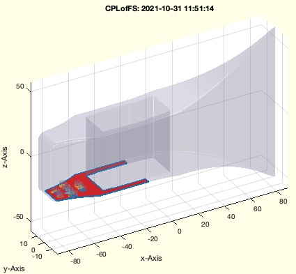 | % CPLofFS(SG,fil) - returns a CPL of a Feature Surface % (by Tim Lueth, VLFL-Lib, 2021-OKT-31 as class: CLOSED POLYGON LISTS) % % mainly the same as CPLofVLFL (Status of: 2021-11-01) % % Introduced first in SolidGeometry 5.1 % % See also: CPLofVLFL % % [CPL,T,ez]=CPLofFS(SG,fil) % === INPUT PARAMETERS === % SG: Solid Geometry % fil: facet index list; or ez vector; % === OUTPUT RESULTS ====== % CPL: CPL % T: Transformation matrix for CVL % ez: ez vector used % % EXAMPLE: %% Hatchet Example for halloween % SGreadSTL('/Users/lueth/Desktop/HalloweenAxe.STL'); N=ans; % CPLofFS(N,FSselect(N,[0 0 -1])); % Using a fil list % CPLofFS(N,[0 0 -1]); % Using a ez vector; % CPLofFS(N); % Interactive mode % % See also: CPLofVLFL % % % Copyright 2021 Tim C. Lueth |
rulerCPL(CPL,ORG,OEZ,SIZ)- plots ruler for a closed polygon list |
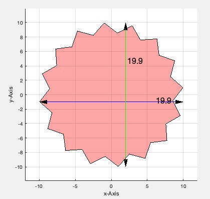 | % rulerCPL(CPL,ORG,OEZ,SIZ) - plots ruler for a closed polygon list % (by Tim Lueth, VLFL-Lib, 2021-OKT-19 as class: VISUALIZATION) % % Introduced first in SolidGeometry 5.1 % % See also: textCPL % % rulerCPL([CPL,ORG,OEZ,SIZ]) % === INPUT PARAMETERS === % CPL: CPL % ORG: Position of ruler; default is center of CPL % OEZ: Second Point for direction % SIZ: size of tip; default is sofBB/20 % % EXAMPLE: % cla; rulerCPL(PLstar(10),[2 -1]); CPSplot(PLstar(10)); shg; % cla; CPSplot(PLstar(10)); pause(1); rulerCPL(PLstar(10)); shg; % cla; CPSplot(PLstar(10)); pause(1); rulerCPL(PLstar(10),[2 -1]); shg; % % See also: textCPL % % % Copyright 2021 Tim C. Lueth |
fontsize(FS,ds)- sets the font size of all text to a specified figure |
 | % fontsize(FS,ds) - sets the font size of all text to a specified figure % (by Tim Lueth, VLFL-Lib, 2021-OKT-12 as class: USER INTERFACE) % % Introduced first in SolidGeometry 5.1 % % See also: SGfigureeval, SGfigurepapermode, papermode, textadjust2gca % % h=fontsize([FS,ds]) % === INPUT PARAMETERS === % FS: default is 16pt on a printout % ds: if true, the font size is adjusted based on the figure size % === OUTPUT RESULTS ====== % h: handle to all text % % EXAMPLE: % % % See also: SGfigureeval, SGfigurepapermode, papermode, textadjust2gca % % % Copyright 2021 Tim C. Lueth |
SGcastplot(SGO,TTO,Name,cols)- creates plots in a cell list wrt to the SGcast type |
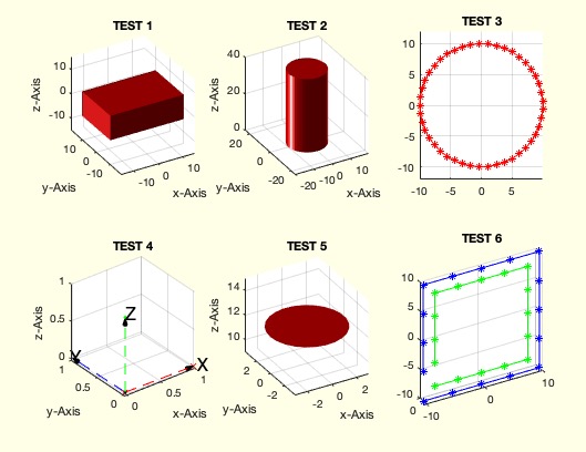 | % SGcastplot(SGO,TTO,Name,cols) - creates plots in a cell list wrt to the SGcast type % (by Tim Lueth, VLFL-Lib, 2021-SEP-14 as class: VISUALIZATION) % % Introduced first in SolidGeometry 5.1 % % See also: SGfeature, SGcast % % SGcastplot(SGO,TTO,Name,[cols]) % === INPUT PARAMETERS === % SGO: Cell list of objects % TTO: type of cell entry; if empty SGcast is used % Name: optinal name as subplot title % cols: color string % % EXAMPLE: % SGcast % C=SGcylinder; C.FIL=FSselect(SGcylinder,[0 0 1],0.1) % CVL=VLtransR(VLaddz(PLcircle(10)),rot([pi/3,pi/3,pi/3])); % SGfigure; SGcastplot({SGbox,SGcylinder(10),PLcircle(10)}) % SGfigure; SGcastplot({SGbox,SGcylinder(10),PLcircle(10)},'','test') % SGfigure; SGcastplot({SGbox,SGcylinder(10),PLcircle(10),eye(4),C,CVLsample(18)},'','test') % SGfigure; SGcastplot({SGbox,SGcylinder(10),PLcircle(10),eye(4),C,CVLsample(18)},'','test','m--',0.1) % % See also: SGfeature, SGcast % % % Copyright 2021 Tim C. Lueth |
SGcast(SG)- class name cast fnct for SG library |
 | % SGcast(SG) - class name cast fnct for SG library % (by Tim Lueth, VLFL-Lib, 2021-SEP-14 as class: AUXILIARY PROCEDURES) % % This fnctn is used to implement complex fnctns similar to an object % oriented (Status of: 2021-09-14) % % Introduced first in SolidGeometry 5.1 % % See also: SGfeature, SGcastplot % % classname=SGcast(SG) % === INPUT PARAMETERS === % SG: Any SG library data type % === OUTPUT RESULTS ====== % classname: SG classname % % EXAMPLE: % A=SGcompass; SGcast({A,A,eye(4),VLaddz(PLcircle(3)),{A,A}}) % SGcast({A,A,eye(4),VLaddz(PLcircle(3)),{A,A},5,PLcircle(3)}') % % See also: SGfeature, SGcastplot % % % Copyright 2021 Tim C. Lueth |
SGcompass- creates a desktop housing for the magnetic compass (look like a Gyro compass) |
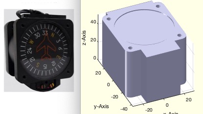 | % SGcompass - creates a desktop housing for the magnetic compass (look like a Gyro compass) % (by Tim Lueth, VLFL-Lib, 2021-SEP-12 as class: MODELING PROCEDURES) % % Introduced first in SolidGeometry 5.1 % % See also: SGjuicermachineclip % % SG=SGcompass % === OUTPUT RESULTS ====== % SG: Just returns the geometry of the compass % % EXAMPLE: % SGcompass % % See also: SGjuicermachineclip % % % Copyright 2021-2022 Tim C. Lueth |
meanT(TL)- returns the man value of a T matrix |
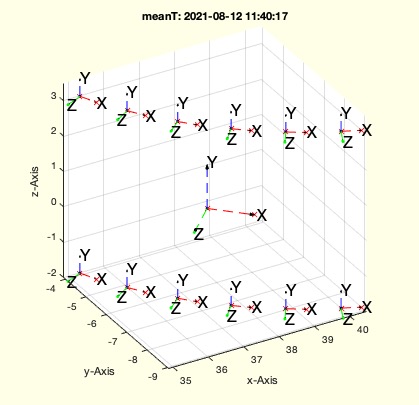 | % meanT(TL) - returns the man value of a T matrix % (by Tim Lueth, VLFL-Lib, 2021-AUG-12 as class: AUXILIARY PROCEDURES) % % Introduced first in SolidGeometry 5.1 % % See also: mean, meanGauss % % T=meanT(TL) % === INPUT PARAMETERS === % TL: cell list or numerical sequence of 4x4 matrices % === OUTPUT RESULTS ====== % T: mean value of a set of HT Matrices % % See also: mean, meanGauss % % % Copyright 2021 Tim C. Lueth |
SGcheck4cura(SG,turn)- Analyzes and checks Solid orientation for printing an a FDM printer |
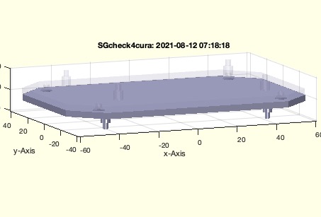 | % SGcheck4cura(SG,turn) - Analyzes and checks Solid orientation for printing an a FDM printer % (by Tim Lueth, VLFL-Lib, 2021-AUG-11 as class: CHECKING PROCEDURES) % % This fnctn analyzes solids or STl files to reduce the rotation of % objects in the program cura % 1. Whether holes are oriented in the direction of the Z axis, % 2. Whether blind holes are also oriented with the opening facing upwards % the fnctn rotates the solids if necessary % in case of STL file, the filename is modified and a rotated copy is % saved. % This fnctn is used in the fnctn "cura" (Status of: 2021-08-12) % % Introduced first in SolidGeometry 5.1 % % See also: cura, gcode2sdcard, CPLofSGboreholes, FSselect, FSfeature % % [SG,fname]=SGcheck4cura([SG,turn]) % === INPUT PARAMETERS === % SG: file name or solid geoemtry % turn: if true, the part is turned; default is true % === OUTPUT RESULTS ====== % SG: Solid Geometry % fname: file name % % EXAMPLE: % SGcheck4cura(SGrotate(SGcylinder(4,10,'',3),'y',pi/2)) % % SGcheck4cura(YKBasePlate) % 3rd case area, Does not work yet 2021-08-12 % % See also: cura, gcode2sdcard, CPLofSGboreholes, FSselect, FSfeature % % % Copyright 2021 Tim C. Lueth |
SGcapontopprojection(SG,T,w,h,sl)- create a simple cap ontop |
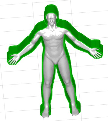 | % SGcapontopprojection(SG,T,w,h,sl) - create a simple cap ontop % (by Tim Lueth, VLFL-Lib, 2021-AUG-11 as class: AUTOMATIC DESIGN) % % Based on the outside projection contour "CPLofSGboreholes", this fnctn % creates a shell with cap (Status of: 2021-08-11) % % Introduced first in SolidGeometry 5.1 % % See also: SGcapontop % % SGN=SGcapontopprojection(SG,[T,w,h,sl]) % === INPUT PARAMETERS === % SG: Solid geometry % T: ez vector for upward, or T matrix % w: widht of shell and cover default is [3 3]; % h: height of shell; default is full length % sl: slot; default is slfit('t') % === OUTPUT RESULTS ====== % SGN: Resulting cap for solid % % EXAMPLE: % load ADAM_Amono.mat % SGcapontopprojection(ADAM_Amono,[0 +1 0],2,20,1) % % See also: SGcapontop % % % Copyright 2021 Tim C. Lueth |
SGservoflange(info,H,sl)- Manually designs a flange connection for a servo motor |
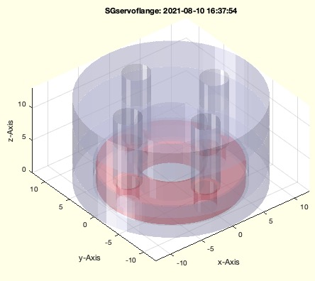 | % SGservoflange(info,H,sl) - Manually designs a flange connection for a servo motor % (by Tim Lueth, VLFL-Lib, 2021-AUG-10 as class: PARAMETRIC DESIGN) % % Do Outer Diameter % Di Inner Diameter % M Screw Diameter % N Number of Screws % W Distance of Screw to Outer Diameter; default is 1mm (Status of: % 2021-08-10) % % Introduced first in SolidGeometry 5.1 % % See also: SGbottleholder, SGrobotTCPdesign % % SG=SGservoflange([info,H,sl]) % === INPUT PARAMETERS === % info: [Do Di M N W] % H: [Height Plate height]; default is [10 0] % sl: slfit ; default is slfit('c') % === OUTPUT RESULTS ====== % SG: Solid Geometry of Part % % EXAMPLE: % SGservoflange('',[10 3]); % SGservoflange('',[10 0]); % % See also: SGbottleholder, SGrobotTCPdesign % % % Copyright 2021 Tim C. Lueth |
Trelation(T,rel)- creates a frame relative to another frame |
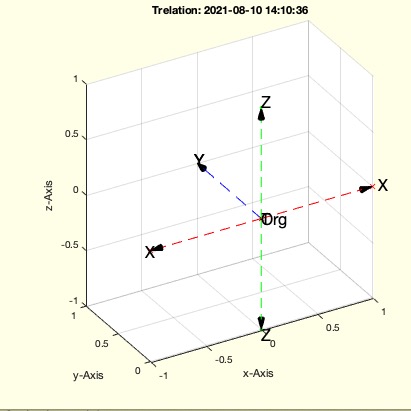 | % Trelation(T,rel) - creates a frame relative to another frame % (by Tim Lueth, VLFL-Lib, 2021-AUG-10 as class: KINEMATICS AND FRAMES) % % 'up','z+','+z', 'down','z-', 'right','x+', 'left','x-','forward','y', % 'backward','y-', 'rotz', 'rotx', 'roty' (Status of: 2021-08-10) % % Introduced first in SolidGeometry 5.1 % % See also: ToftransrelSG, TofTrel % % T=Trelation([T,rel]) % === INPUT PARAMETERS === % T: Frame; default is eye(4) % rel: sequence of spatial relations % === OUTPUT RESULTS ====== % T: resulting HT frame % % EXAMPLE: % Trelation(TofPez([5 0 0],[0 -1 0]),'up',4) % Trelation(TofPez([5 0 0],[0 -1 0]),'up',4,'left',1) % % See also: ToftransrelSG, TofTrel % % % Copyright 2021 Tim C. Lueth |
TofCVLdimclassifier(CVL,minmaxR,minmaxW,ez);- returns Frames for radii in 3D-Contours as CVL |
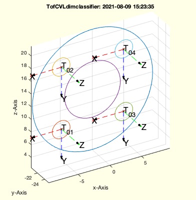 | % TofCVLdimclassifier(CVL,minmaxR,minmaxW,ez); - returns Frames for radii in 3D-Contours as CVL % (by Tim Lueth, VLFL-Lib, 2021-AUG-09 as class: KINEMATICS AND FRAMES) % % Different to TofCVL % Similar to SGTsetofRL, but intened for with CVL 3D-Contours (Status of: % 2021-08-09) % % Introduced first in SolidGeometry 5.1 % % See also: SGTsetofRL, TofCVL % % TofCVLdimclassifier(CVL,[minmaxR,minmaxW,ez]); % === INPUT PARAMETERS === % CVL: 3D-Contours % minmaxR: mimimal and maximal radius to consider default is [1.25 10] % minmaxW: minimal & maxium circum angle to consider; default is [40 360] % ez: force ez vector % % EXAMPLE: % load Yannick_robot.mat % SG=YKLowerServo; SG= SGrotate(SG,'x') % FSselect(SG,[0 -1 0],'numholes',5); fil=ans; % FSfeature(SG,fil,'cvl'); cvl=ans; % TofCVLdimclassifier(cvl,[0 4]), cell2mat(ans) % % TofCVLdimclassifier(CPLbuffer(PLsquare(10),2,'round'),[0 4]), cell2mat(ans) % % See also: SGTsetofRL, TofCVL % % % Copyright 2021 Tim C. Lueth |
SGcopyTL(SG,TL,rel)- copies a solid using a cell list of frames |
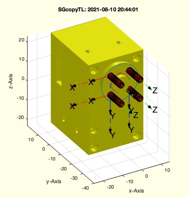 | % SGcopyTL(SG,TL,rel) - copies a solid using a cell list of frames % (by Tim Lueth, VLFL-Lib, 2021-AUG-09 as class: SURFACES) % % Introduced first in SolidGeometry 5.1 % % See also: SGcopyVL, CPLcopypatternTL, SGcopyrotZ, SGcopypatternXYZ, % Trelation % % SGC=SGcopyTL(SG,TL,[rel]) % === INPUT PARAMETERS === % SG: Solid Geometry to copy % TL: List of Frames % rel: spatial relations for Trelation % === OUTPUT RESULTS ====== % SGC: Solid including all copies of TL % % EXAMPLE: % load Yannick_robot.mat % SG=YKLowerServo; SG= SGrotate(SG,'x') % FSselect(SG,[0 -1 0],'numholes',5); fil=ans; % FSfeature(SG,fil,'cvl'); cvl=ans; % TofCVLdimclassifier(cvl,[0 4]); TL=ans, cell2mat(ans) % % SGcopyTL(SGcylinder(1.5,10),TL); SGplotalpha(SG,'y',0.2); CVLplot(cvl,'-'); tplot(TL,20); % SGcopyTL(SGcylinder(1.5,10),TL,'down',3); SGc=ans; CVLplot(cvl,'-',2); tplot(TL,20); % SGsubtract(SG,SGc) % % % See also: SGcopyVL, CPLcopypatternTL, SGcopyrotZ, SGcopypatternXYZ, % Trelation % % % Copyright 2021 Tim C. Lueth |
CPLunsort(CPL)- changes the order of nan separated CPL using unsortNaN |
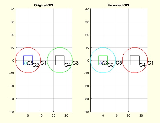 | % CPLunsort(CPL) - changes the order of nan separated CPL using unsortNaN % (by Tim Lueth, VLFL-Lib, 2021-AUG-06 as class: CLOSED POLYGON LISTS) % % Mainly for testing other fnctn such as CPLregions (Status of: % 2021-08-06) % % Introduced first in SolidGeometry 5.1 % % See also: unsortNaN % % CPLU=CPLunsort(CPL) % === INPUT PARAMETERS === % CPL: Original CPL % === OUTPUT RESULTS ====== % CPLU: THe order of Conturs has changed % % EXAMPLE: % CPLunsort(CPLsample(27)) % % See also: unsortNaN % % % Copyright 2021 Tim C. Lueth |
CPLregions(CPL)- sorts a CPL with respect to regions |
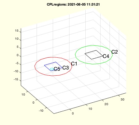 | % CPLregions(CPL) - sorts a CPL with respect to regions % (by Tim Lueth, VLFL-Lib, 2021-AUG-05 as class: CLOSED POLYGON LISTS) % % mainly same as CPLsortinout (Status of: 2021-08-05) % % Introduced first in SolidGeometry 5.1 % % See also: CPLsortinout, CPLselectinout % % [CPLN,PiL]=CPLregions(CPL) % === INPUT PARAMETERS === % CPL: Closed Polygon Line % === OUTPUT RESULTS ====== % CPLN: Sorten to regions % PiL: [parent-index of CPLN, region leve, 0 = outsidel] % % EXAMPLE: % CPLregions(CPLsample(27)); % % See also: CPLsortinout, CPLselectinout % % % Copyright 2021 Tim C. Lueth |
SGofCPLzrotxy(CPL,z,w)- rotates a CPL and extrudes in z |
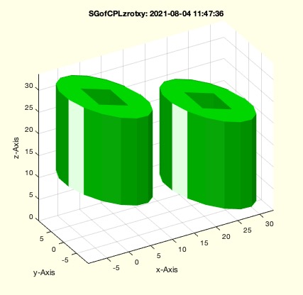 | % SGofCPLzrotxy(CPL,z,w) - rotates a CPL and extrudes in z % (by Tim Lueth, VLFL-Lib, 2021-AUG-04 as class: MODELING PROCEDURES) % % Introduced first in SolidGeometry 5.1 % % See also: SGofCPLz % % SG=SGofCPLzrotxy(CPL,[z,w]) % === INPUT PARAMETERS === % CPL: CPL % z: height % w: roatation angle in [x y z] % === OUTPUT RESULTS ====== % SG: Solid Geometry % % EXAMPLE: % SGofCPLzrotxy (PLsquare([20 40]),50,[0 pi/10 0]) % SGofCPLzrotxy (PLsquare([20 40]),50,[0 pi/10 pi/4]) % SGofCPLzrotxy (CPLsample(12),50,[0 pi/10]) % % See also: SGofCPLz % % % Copyright 2021 Tim C. Lueth |
SGbanditjethelmclip- creates a clip for a Bandit Jet Helmet |
 | % SGbanditjethelmclip - creates a clip for a Bandit Jet Helmet % (by Tim Lueth, VLFL-Lib, 2021-JUL-28 as class: MODELING PROCEDURES) % % Introduced first in SolidGeometry 5.1 % % See also: SGofCPLcommand % % SGbanditjethelmclip % % See also: SGofCPLcommand % % % Copyright 2021 Tim C. Lueth |
PLcircleofPL(CPL)- returns minimal and maximal circle around a CPL |
 | % PLcircleofPL(CPL) - returns minimal and maximal circle around a CPL % (by Tim Lueth, VLFL-Lib, 2021-JUL-28 as class: CLOSED POLYGON LISTS) % % Introduced first in SolidGeometry 5.1 % % See also: PLcircle % % [PLCmax,PLCmin,rmax,rmin,cp]=PLcircleofPL(CPL) % === INPUT PARAMETERS === % CPL: CPL % === OUTPUT RESULTS ====== % PLCmax: PLcircle(Rmax) % PLCmin: PLcircle(Rmin) % rmax: rmax % rmin: rmin % cp: cp % % EXAMPLE: % PLcircleofPL(CPLsample(3)) % % See also: PLcircle % % % Copyright 2021-2022 Tim C. Lueth |
VLFLregions(VL,FL,FIL)- fnct to separate regions in face index list |
 | % VLFLregions(VL,FL,FIL) - fnct to separate regions in face index list % (by Tim Lueth, VLFL-Lib, 2021-JUL-27 as class: SURFACES) % % This is the modern version of VLFLseparate. It is used for instance in % FSofSGnormal. % Following the terms of Matlab in the polyshape classe, I now also use % the term regions for surfaces that are connected to each other. In % previous versions, only the term VLFLseparate or SGseparate was used. % Based on FLorder (Status of: 2021-07-27) % % Introduced first in SolidGeometry 5.1 % % See also: SGseparate, SGsurfaces, FLorder % % fil=VLFLregions(VL,FL,[FIL]) % === INPUT PARAMETERS === % VL: Vertex list % FL: Facet list % FIL: ONE facet index list; default is 1:size(FL,1) % === OUTPUT RESULTS ====== % fil: cell list for separated regions % % See also: SGseparate, SGsurfaces, FLorder % % % Copyright 2021 Tim C. Lueth |
FSfeature(SG,FIL,feat)- Selects features surfaces based on |
 | % FSfeature(SG,FIL,feat) - Selects features surfaces based on % (by Tim Lueth, VLFL-Lib, 2021-JUL-15 as class: SURFACES) % % There are several fnctns for the selection of surfaces, features, and % frames % FSofSGnormal - uses a normal vector for the selection % FSselect - should simply select surfaces out of a larger set of surfaces % FSfeature - should return properties of different data types % see also all SGTset fnctns % ======================================================================= % The 3rd of a set of fnctns aimed directly at the analysis and formal % specification of surfaces. This is necessary to give a clear structure % to the formal addressing of surfaces. Concept similar to TofSG % 1) FSofSGnormal - FIL wrt to a normal vector % 2) FSselect - FIL as selection based on features % 3) FSfeature - Different data types wrt to feature request % % Feature request: % "cp" Center point % "ez" Normla vector % "area" Area size % "numholes" Number of holes % "T" Center Frame % (Status of: 2021-09-13) % % Introduced first in SolidGeometry 5.1 % % See also: FSofSGnormal, FSselect, FSofSG, FSofSGfacet, % TofCVLdimclassifier % % F=FSfeature(SG,FIL,[feat]) % === INPUT PARAMETERS === % SG: Solid Geometry % FIL: Cell list of facet indices % feat: feature request string % === OUTPUT RESULTS ====== % F: Result as cell list; scalars, vectors, frames, etc. % % EXAMPLE: % load JACO_robot.mat % FSselect(JC0,[1 0 0],0.4,'areamin',100); FIL=ans; % FSfeature(JC0,FIL,'numholes'); cell2mat(ans) % % See also: FSofSGnormal, FSselect, FSofSG, FSofSGfacet, % TofCVLdimclassifier % % % Copyright 2021 Tim C. Lueth |
FSofSGnormal(TR,nv,alp,rec)- finds all feature surfaces that fullfil the same normal vector condition |
 | % FSofSGnormal(TR,nv,alp,rec) - finds all feature surfaces that fullfil the same normal vector condition % (by Tim Lueth, VLFL-Lib, 2021-JUL-14 as class: SURFACES) % % There are several fnctns for the selection of surfaces, features, and % frames % FSofSGnormal - uses a normal vector for the selection % FSselect - should simply select surfaces out of a larger set of surfaces % FSfeature - should return properties of different data types % see also all SGTset fnctns % ======================================================================= % The 1st of a set of fnctns aimed directly at the analysis and formal % specification of surfaces. This is necessary to give a clear structure % to the formal addressing of surfaces (Status of: 2021-09-13) % % Introduced first in SolidGeometry 5.1 % % See also: FSofSGfacet, FSselect, FSfeature % % [FILk,FILm,FILi]=FSofSGnormal(TR,[nv,alp,rec]) % === INPUT PARAMETERS === % TR: Triangulation or SG % nv: normal vector; default is [0 0 1] % alp: alpha angle; default is 0.01 % rec: if false, alpha is also the absolut limit to the nv vector; % default is true; % === OUTPUT RESULTS ====== % FILk: Cell list of facets that belong to the same feature surface % FILm: Cell list of facets that belong to the same feature surface but % are most similar to nv % FILi: Cell list of one facet per surface that is most similar to nv % % EXAMPLE: % load JACO_robot.mat % FSofSGnormal(JC0,[0 0 1]) % FSofSGnormal(SGsample(44),[0 0 1]) % FSofSGnormal(SGsphere(100),[0 0 1],pi/20,true) % FSofSGnormal(SGsphere(100),[0 0 1],pi/20,false) % % See also: FSofSGfacet, FSselect, FSfeature % % % Copyright 2021 Tim C. Lueth |
FSselect(SG,FIL,rel)- Selects features surfaces based on |
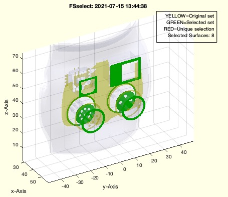 | % FSselect(SG,FIL,rel) - Selects features surfaces based on % (by Tim Lueth, VLFL-Lib, 2021-JUL-14 as class: SURFACES) % % There are several fnctns for the selection of surfaces, features, and % frames % FSofSGnormal - uses a normal vector for the selection % FSselect - should simply select surfaces out of a larger set of surfaces % FSfeature - should return properties of different data types % see also all SGTset fnctns % ======================================================================= % The 2nd of a set of fnctns aimed directly at the analysis and formal % specification of surfaces. This is necessary to give a clear structure % to the formal addressing of surfaces. Concept similar to TofSG % There are some features that only run on one surface, but also others % that combine multiple surfaces. Maybe this will become a fourth fnctn. % Current implemented selectors 'sizedescend', 'sizeascend', 'sizemin', % 'sizemax', 'front','back', 'numholes'' % % (Status of: 2021-09-13) % % Introduced first in SolidGeometry 5.1 % % See also: FSofSGnormal, FSofSG, FSofSGfacet % % FILN=FSselect(SG,FIL,[rel]) % === INPUT PARAMETERS === % SG: Solid Geometry % FIL: Cell list of facet indices, or normal vector for FSofSGnormal % rel: list of descriptors, can also start with an angle of FIL is a % normal vector % === OUTPUT RESULTS ====== % FILN: unsorted cell list of FILs for the selected surfaces % % EXAMPLE: % load JACO_robot.mat % FSofSGnormal(JC0,[0 0 1]); FIL=ans % FSofSGnormal(JC0,[1 0 0]); FIL=ans % FSselect(JC0,FIL,'areamax',400,'areadescend',1:10,'holesnum',1:10); % FSselect(JC0,[1 0 0],'areamax',400,'areadescend',1:10,'holesnum',1:10); % FSselect(JC0,[1 0 0],pi/2.2,'areamax',400,'areadescend',1:10,'holesnum',1:10); % FSselect(JC0,[1 0 0],pi/2.2,'areamax',400,'areadescend',1:10,'holesnum',1:10,'front',1:2); % 1 and 2 % FSselect(JC0,[1 0 0],pi/2.2,'areamax',400,'areadescend',1:10,'holesnum',1:10,'front',-5); % 5mm distance % % See also: FSofSGnormal, FSofSG, FSofSGfacet % % % Copyright 2021 Tim C. Lueth |
SGdesignrules- Tim Lueth's design rules for creating 3D printable products for daily living |
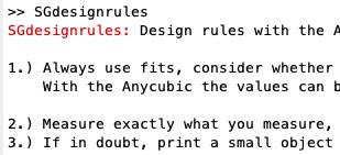 | % SGdesignrules - Tim Lueth's design rules for creating 3D printable products for daily living % (by Tim Lueth, VLFL-Lib, 2021-JUL-13 as class: MODELING PROCEDURES) % % This helptext can be copied into the clipboard and inserted as code by % paste2code: I write in German and translate it using deepL. Comment % signs at line starts are filtered. % The original Text is a second comment block in the code, that can be % changed in the matlab editor. % (Status of: 2021-07-13) % % Introduced first in SolidGeometry 5.1 % % See also: paste2code % % SGdesignrules % % EXAMPLE: % SGdesignrules % % See also: paste2code % % % Copyright 2021 Tim C. Lueth |
SGbottleholder(D,L,B,H,n);- returns the geometry of a simple bottle holder |
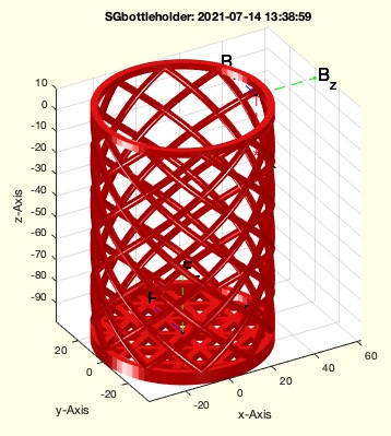 | % SGbottleholder(D,L,B,H,n); - returns the geometry of a simple bottle holder % (by Tim Lueth, VLFL-Lib, 2021-JUL-12 as class: MODELING PROCEDURES) % % This fnctn uses slfit to be adaptive to different 3D Printers (Status % of: 2021-07-13) % % Introduced first in SolidGeometry 5.1 % % See also: SGrobotTCPdesign % % SA=SGbottleholder([D,L,B,H,n]); % === INPUT PARAMETERS === % D: Diameter of the bottle; default is 68mm % L: Length of the Hold % B: Wall tickness of all elements; default is 3 % H: Height of the rings and struts % n: number of struts % === OUTPUT RESULTS ====== % SA: Geometry of the bottle holder with Frames 'B' and 'F' % % EXAMPLE: % SGbottleholder(68,40,3,10,3) % SGbottleholder(68,106,3,10,7) % % See also: SGrobotTCPdesign % % % Copyright 2021 Tim C. Lueth |
TofBB(BB,listofrel)- returns frames relative to bounding boxes |
 | % TofBB(BB,listofrel) - returns frames relative to bounding boxes % (by Tim Lueth, VLFL-Lib, 2021-JUL-12 as class: KINEMATICS AND FRAMES) % % calls the fnctn TofSG of 27.11.2016 % modified 2022-05-01 (Status of: 2022-05-01) % % Introduced first in SolidGeometry 5.1 % % See also: TofSG % % T=TofBB(BB,[listofrel]) % === INPUT PARAMETERS === % BB: Bounding Box or cell list of Bounding boxes % listofrel: list of relation such as 'under', {disp, ez, rotz} % === OUTPUT RESULTS ====== % T: Frame or cell list of frames % % EXAMPLE: % clc; TofBB(SGbox,'under',{10,[0 -1 0],pi/10}) % % See also: TofSG % % % Copyright 2021-2022 Tim C. Lueth |
SGrobotTCPdesign(SG,TN,d)- Tutorial fnct to design Robot Tools |
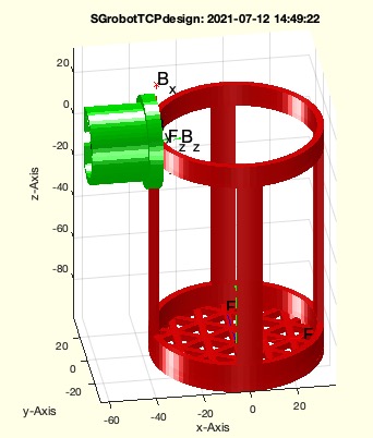 | % SGrobotTCPdesign(SG,TN,d) - Tutorial fnct to design Robot Tools % (by Tim Lueth, VLFL-Lib, 2021-JUL-07 as class: MODELING PROCEDURES) % % For the turn of the year 2020/2021, I have designed a quick-change % adapter for the robot (SGrobotTCPchanger fnctn). This can be mounted % directly on the SERVO flange via 4 cylinder head screws. The next step % is to design tools for different tasks as quickly as possible. The % simplest method is to design a gripper or a tool and to attach the % adapter to the component via a position/frame/mouse click. (Status of: % 2021-07-12) % % Introduced first in SolidGeometry 5.1 % % See also: SGrobotTCPchanger % % [TCPtool]=SGrobotTCPdesign(SG,TN,[d]) % === INPUT PARAMETERS === % SG: Solid Geometry to mount to TCPtool % TN: Frame Name at SG to move TCPtool to % d: distance to adjust TCP tool % === OUTPUT RESULTS ====== % [TCPtool]: Just the Tool % % EXAMPLE: % SH=SGbottleholder; SGrobotTCPdesign(SH,'B'); SA=ans; SGwriteSTL(SGconcat(SA,SH)) % % % See also: SGrobotTCPchanger % % % Copyright 2021 Tim C. Lueth |
Tofselect3d(SG,pfi,alp,mbf,Text)- Select interactively FS, surface, and complete solids |
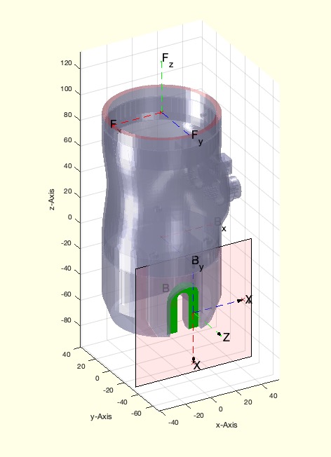 | % Tofselect3d(SG,pfi,alp,mbf,Text) - Select interactively FS, surface, and complete solids % (by Tim Lueth, VLFL-Lib, 2021-JUN-29 as class: EXPERIMENTS) % % identical to SGselect3Dsurface and fiofselect3d but different return % values % 1 = left mouse button = feature surface % 3 = right mouse button = complete surface % 2 = middle mouse button/wheel = solid geometry that belongs to object % (Status of: 2021-06-29) % % Introduced first in SolidGeometry 5.1 % % See also: SGselect3d, SGselect3dPL, select3d, SGselect3Dsurface, % fiofselect3d % % [T,fi,fil,pp]=Tofselect3d([SG,pfi,alp,mbf,Text]) % === INPUT PARAMETERS === % SG: Solid Geometry; if empty SGofgca is used % pfi: optional already preselected facet index % alp: angle to select faces % mbf: force button mode 1, 2, 3 % Text: Optional text for the header of the windows % === OUTPUT RESULTS ====== % T: touched facet index % fi: Facet index list that belongs to touched graphics object % fil: Frame of FS % pp: % % EXAMPLE: % loadweb JACO_robot.mat % Tofselect3d(JC0,'','','','PLEASE BE ASTONISHD') % % See also: SGselect3d, SGselect3dPL, select3d, SGselect3Dsurface, % fiofselect3d % % % Copyright 2021 Tim C. Lueth |
CListype(CL,ind)- returns the type of correlation link |
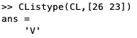 | % CListype(CL,ind) - returns the type of correlation link % (by Tim Lueth, VLFL-Lib, 2021-MAI-01 as class: CLOSED POLYGON LISTS) % % required if the CL list in manipulated for optimization % I == 1:1 % A == n:1 % V == 1:n % requests of type [ai bi], [nan bi], [ai nan] (Status of: 2021-05-01) % % Introduced first in SolidGeometry 5.1 % % See also: CLofFLW % % [res,ind]=CListype(CL,ind) % === INPUT PARAMETERS === % CL: Correlation list % ind: [ai bi], [nan bi], [ai nan] % === OUTPUT RESULTS ====== % res: Type of link % ind: % % EXAMPLE: % [SG,FLW]=SGof2CPLz(CPLsample(17),CPLsample(18),100); CL=CLofFLW(FLW); % CListype(CL,[nan nan]) % CListype(CL,[1 nan]) % I-Type % CListype(CL,[4 nan]) % A-Type % CListype(CL,[9 nan]) % V-Type % CListype(CL,[nan 1]) % I-Type % CListype(CL,[nan 2]) % A-Type % CListype(CL,[nan 3]) % V-Type % CListype(CL,[26 22]) 5 Does not exist % % See also: CLofFLW % % % Copyright 2021 Tim C. Lueth |
papermode()- removes picture title and increases font size for publications |
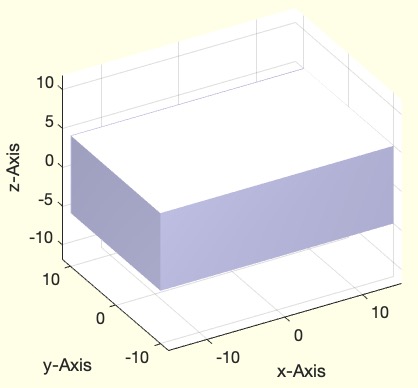 | % papermode() - removes picture title and increases font size for publications % (by Tim Lueth and Yilun Sun, VLFL-Lib, 2021-APR-29 as class: USER % INTERFACE) % % SAME AS SGfigurepapermode (Status of: 2021-12-10) % % Introduced first in SolidGeometry 5.1 % % See also: SGfigureeval, SGfigurepapermode, fontsize % % papermode([]) % % EXAMPLE: % SGfigure(SGbox) % SGfigurepapermode % % See also: SGfigureeval, SGfigurepapermode, fontsize % % % Copyright 2021 Tim C. Lueth |
CLsortrows(CL)- Sorts a corrleation list |
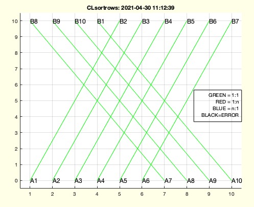 | % CLsortrows(CL) - Sorts a corrleation list % (by Tim Lueth, VLFL-Lib, 2021-APR-29 as class: CLOSED POLYGON LISTS) % % Use ELunsort to check (Status of: 2021-04-30) % % Introduced first in SolidGeometry 5.1 % % See also: CLofFLW, PLcorrelationcheck, CLplot % % CL=CLsortrows(CL) % === INPUT PARAMETERS === % CL: Correlation list % === OUTPUT RESULTS ====== % CL: Sorted Correlation list % % EXAMPLE: % [SG,FLW]=SGofCPLz(PLcircle(10,10),20); CL=CLofFLW(FLW), [PLA,PLNB]=PLofCL(CL); % CLN=ELunsort(CL), CLsortrows(CL) % % See also: CLofFLW, PLcorrelationcheck, CLplot % % % Copyright 2021 Tim C. Lueth |
CLplot(CL,w)- plots a correlation for debugging (same as plotcorrelation) |
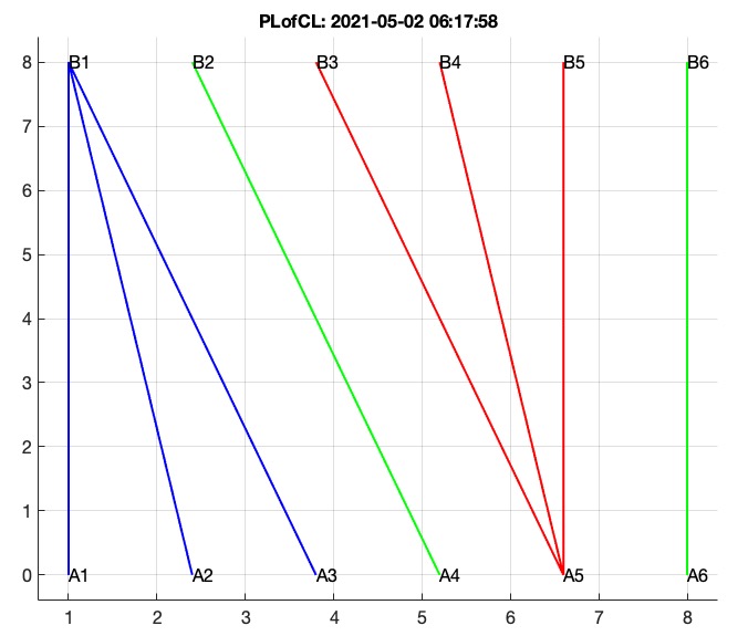 | % CLplot(CL,w) - plots a correlation for debugging (same as plotcorrelation) % (by Tim Lueth, VLFL-Lib, 2021-APR-29 as class: CLOSED POLYGON LISTS) % % more or less for debugging % graphofEL => Shows just CL % plotcorrelation => 2D view % PLplotcorrelation => CL plus Point information % (Status of: 2021-05-02) % % Introduced first in SolidGeometry 5.1 % % See also: FLofPLcorrelation, PLcorrelationcheck, plotcorrelation, % PLplotcorrelation % % CLplot(CL,[w]) % === INPUT PARAMETERS === % CL: Corrleation list (or FL) % w: Widht of lines % % EXAMPLE: % cla; CLplot([1 1;2 1;3 1; 4 2; 5 3 ; 5 4; 5 5; 6 6],2); plotannotationdelete; papermode % % See also: FLofPLcorrelation, PLcorrelationcheck, plotcorrelation, % PLplotcorrelation % % % Copyright 2021 Tim C. Lueth |
PLofCL(CL)- returns an arbitrary planar point list to vizualize the correspondance list |
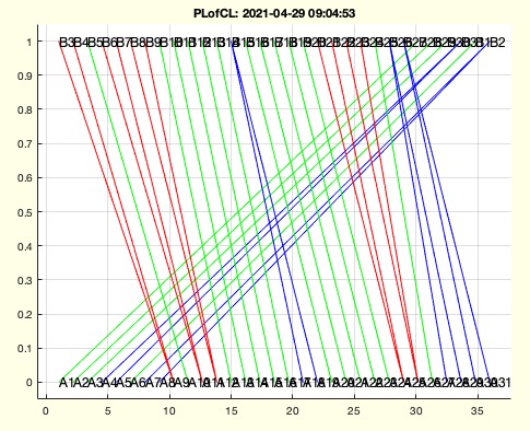 | % PLofCL(CL) - returns an arbitrary planar point list to vizualize the correspondance list % (by Tim Lueth, VLFL-Lib, 2021-APR-29 as class: CLOSED POLYGON LISTS) % % extracted from PLplotcorrelation (Status of: 2021-04-29) % % Introduced first in SolidGeometry 5.1 % % See also: PLplotcorrelation % % [PL1,PL2]=PLofCL(CL) % === INPUT PARAMETERS === % CL: Correspondance list % === OUTPUT RESULTS ====== % PL1: Point list belongst to 1st col of CL % PL2: Point list belongst to 2nd col of CL % % EXAMPLE: % [SG,FLW]=SGof2CPLz(CPLsample(17),CPLsample(18),100); % CL=CLofFLW(FLW) % [PLA,PLB]=PLofCL(CL) % % % % See also: PLplotcorrelation % % % Copyright 2021 Tim C. Lueth |
CLofFLW(FLW)- returns a correlation list from a facet list between 2 free boundaries |
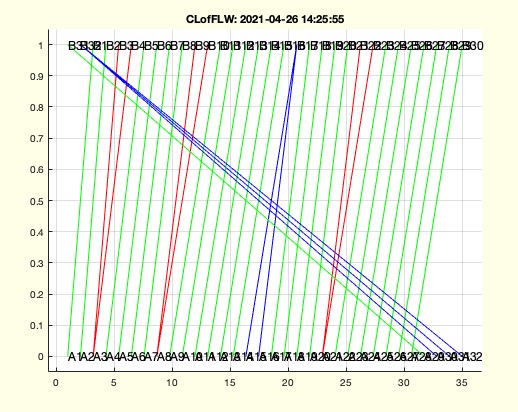 | % CLofFLW(FLW) - returns a correlation list from a facet list between 2 free boundaries % (by Tim Lueth, VLFL-Lib, 2021-APR-26 as class: CLOSED POLYGON LISTS) % % inverse fnctn to FLofPLcorrelation (Status of: 2021-04-28) % % Introduced first in SolidGeometry 5.1 % % See also: FLofPLcorrelation, CLplot, PLcorrelationcheck % % CL=CLofFLW(FLW) % === INPUT PARAMETERS === % FLW: Facet list of a wall between two free boundary contours % === OUTPUT RESULTS ====== % CL: Correspondance list % % EXAMPLE: % [CL,VL]=PLcorrelatingsegments(CPLsample(17),CPLsample(18)); % FLofPLcorrelation(CL,'',VL); FLW=ans; % FLofPLcorrelation(CL); FLW=ans; % CLofFLW(FLW); CLN=ans % % See also: FLofPLcorrelation, CLplot, PLcorrelationcheck % % % Copyright 2021 Tim C. Lueth |
plotcorrelation(CL)- plots a correlation for debugging |
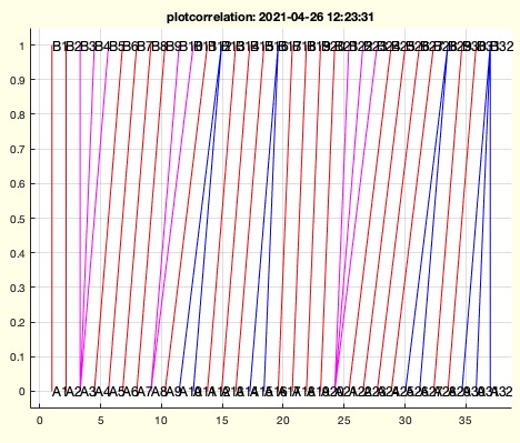 | % plotcorrelation(CL) - plots a correlation for debugging % (by Tim Lueth, VLFL-Lib, 2021-APR-20 as class: CLOSED POLYGON LISTS) % % more or less for debugging % graphofEL => Shows just CL % plotcorrelation => 2D view % PLplotcorrelation => CL plus Point information % (Status of: 2021-04-26) % % Introduced first in SolidGeometry 5.1 % % See also: FLofPLcorrelation, PLcorrelationcheck, PLplotcorrelation % % plotcorrelation(CL) % === INPUT PARAMETERS === % CL: Corrleation list (or FL) % % EXAMPLE: % EL=CL; EL(:,2)=EL(:,2)+max(EL(:,1)); graphofEL(EL); % [CL,VL]=PLcorrelate(CPLsample(3),PLcircle(10,4)); % plotcorrelation(CL) % [CL,VL]=PLcorrelatingsegments(CPLsample(17),CPLsample(18)); % plotcorrelation(CL) % % See also: FLofPLcorrelation, PLcorrelationcheck, PLplotcorrelation % % % Copyright 2021 Tim C. Lueth |
paste2code(n)- if called on the commandwindow, it returns the contant of the clipboard as matlab code |
 | % paste2code(n) - if called on the commandwindow, it returns the contant of the clipboard as matlab code % (by Tim Lueth, VLFL-Lib, 2021-APR-17 as class: AUXILIARY PROCEDURES) % % It is possible to generate a keyboard macro like Command-Shift-V that % opens the command window A (Command-Zero) and types paste2code. Then it % is possible % 1. to mark any Text in the editor (for example as comment) % 2. Use Deep-L for translation % 3. Use Command-Shift-V to create the source code in the command window % (and to insert it into the past buffer % 4. Copy it into the editor (Status of: 2021-04-18) % % Introduced first in SolidGeometry 5.1 % % See also: textHorizontalBlockAlign, str2codelines, paste2code., % clipboardrem, clipboardadd % % % text=paste2code([n]) % === INPUT PARAMETERS === % n: number of chars per line; default is 112; % === OUTPUT RESULTS ====== % text: text from the clipbord % % EXAMPLE: Copy the follwowing help text into clip bey by command-C/control c and call paste2code in the commandwindow % % 1. you can actually translate this text into English. % % 2. once the translation has been copied to the clipboard, you can % % 3. get the lines for the source code in the commandwindow by using the command past2code. % % 4. copy the lines from the commandwindo into the source code % % See also: textHorizontalBlockAlign, str2codelines, paste2code., % clipboardrem, clipboardadd % % % % Copyright 2021 Tim C. Lueth |
VLFLoptimizeFLWez(VL,FL)- finds the surfaces correlation that creates the largest volume |
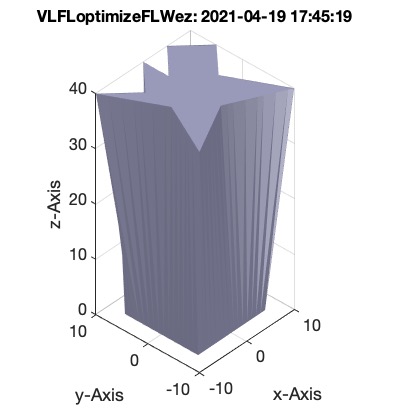 | % VLFLoptimizeFLWez(VL,FL) - finds the surfaces correlation that creates the largest volume % (by Tim Lueth, VLFL-Lib, 2021-APR-16 as class: SURFACES) % % was part of exp_2021_04_16_FLcorrelate % (Status of: 2021-04-19) % % Introduced first in SolidGeometry 5.1 % % See also: VLFLfreeboundarycircshift, FLofPLcorrelation, PLcorrelate, % PLcorrelatingsegments, SGof2CPLz % % [FLN,VLN]=VLFLoptimizeFLWez(VL,FL) % === INPUT PARAMETERS === % VL: Vertex List % FL: Facet list % === OUTPUT RESULTS ====== % FLN: New Facet list wrt to original Vertex list % VLN: New Vertex list wrt to original Facet list % % EXAMPLE: % [SG,FLW,FLA,FLB]=SGof2CPLz(CPLaddauxpoints(CPLsample(2),1),CPLaddauxpoints(CPLsample(3),1),40); % VLFLoptimizeFLWez(SG.VL,FLW); FLW=ans; % SG.FL=[FLW;FLA;FLB]; cla; SGplotalpha(SG,'w',1,'k') % % See also: VLFLfreeboundarycircshift, FLofPLcorrelation, PLcorrelate, % PLcorrelatingsegments, SGof2CPLz % % % Copyright 2021 Tim C. Lueth |
VLFLfreeboundarycircshift(VL,FL,k)- changes Vertices or Facets to achieve a free boundary rotation |
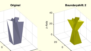 | % VLFLfreeboundarycircshift(VL,FL,k) - changes Vertices or Facets to achieve a free boundary rotation % (by Tim Lueth, VLFL-Lib, 2021-APR-16 as class: SURFACES) % % was part of exp_2021_04_16_FLcorrelate % (Status of: 2021-04-19) % % Introduced first in SolidGeometry 5.1 % % See also: VLFLoptimizeFLWez, FLofPLcorrelation, PLplotcorrelation, % PLcorrelationcheck, SGof2CPLz % % [VLN,nE,FLN]=VLFLfreeboundarycircshift(VL,FL,[k]) % === INPUT PARAMETERS === % VL: Vertex List % FL: Facet list with exact TWO open boundaries % k: shift number; default is 1 % === OUTPUT RESULTS ====== % VLN: New Vertex list wrt to old facet list % nE: number of changes % FLN: New Facet list wrt to old vertex list % % EXAMPLE: % VLFLfreeboundarycircshift(SG.VL,FLW,1); % VLFLfreeboundarycircshift(SG.VL,FLW,2); % VLFLfreeboundarycircshift(SG.VL,FLW,3); % VLFLfreeboundarycircshift(SG.VL,FLW,-2); % % See also: VLFLoptimizeFLWez, FLofPLcorrelation, PLplotcorrelation, % PLcorrelationcheck, SGof2CPLz % % % Copyright 2021 Tim C. Lueth |
scalesequence(x,n,usemean)- returns a streched sequence between an minimal and maximal value |
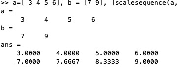 | % scalesequence(x,n,usemean) - returns a streched sequence between an minimal and maximal value % (by Tim Lueth, VLFL-Lib, 2021-APR-16 as class: AUXILIARY PROCEDURES) % % seemed to be simple, but the exception cases are more complex, so it % makes to have an own fnctn (Status of: 2021-04-16) % % Introduced first in SolidGeometry 5.1 % % See also: mod1circsequ % % y=scalesequence(x,n,[usemean]) % === INPUT PARAMETERS === % x: value sequence - only first and last values are used % n: number of desired values % usemean: use mean value if n==1 and numel(unique(x))>1; default is false % === OUTPUT RESULTS ====== % y: new sequence as [1 x n] row vector % % EXAMPLE: % scalesequence([3 4],1) % scalesequence([3 4],2) % scalesequence([3 4],3) % a=[ 3 4 5 6], b = [7 9], [scalesequence(a,max(numel(a),numel(b))); scalesequence(b,max(numel(a),numel(b)))] % % See also: mod1circsequ % % % Copyright 2021 Tim C. Lueth |
PLplotcorrelation(CL,CPLA,CPLB,col,wdt,ss,z)- simply plots a point list correlation |
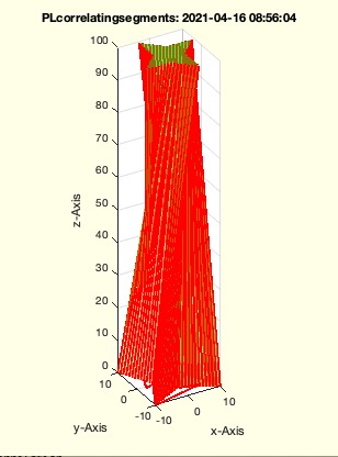 | % PLplotcorrelation(CL,CPLA,CPLB,col,wdt,ss,z) - simply plots a point list correlation % (by Tim Lueth, VLFL-Lib, 2021-APR-15 as class: VISUALIZATION) % % also performs an PLcorrelationcheck (Status of: 2021-04-16) % % Introduced first in SolidGeometry 5.1 % % See also: FLofPLcorrelation, PLcorrelationcheck, plotcorrelation % % PLplotcorrelation(CL,CPLA,CPLB,[col,wdt,ss,z]) % === INPUT PARAMETERS === % CL: CL see PLcorrelate % CPLA: CPLA % CPLB: CPLB % col: color; default is 'r-' % wdt: width; default is 2 % ss: selection of rows in CL % z: specific z difference % % EXAMPLE: % CL=PLcorrelatingsegments(CPLsample(3),CPLsample(6)); % cla; PLplotcorrelation(CL,CPLsample(3),CPLsample(6)) % % See also: FLofPLcorrelation, PLcorrelationcheck, plotcorrelation % % % Copyright 2021 Tim C. Lueth |
PLcorrelationcheck(CL,CPLA,CPLB,text)- important fnct to detect problems that are difficult to see for a human |
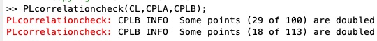 | % PLcorrelationcheck(CL,CPLA,CPLB,text) - important fnct to detect problems that are difficult to see for a human % (by Tim Lueth, VLFL-Lib, 2021-APR-15 as class: CLOSED POLYGON LISTS) % % used in PLcorrelation (Status of: 2021-04-15) % % Introduced first in SolidGeometry 5.1 % % See also: PLcorrelate, ismonotonously % % err=PLcorrelationcheck(CL,CPLA,CPLB,[text]) % === INPUT PARAMETERS === % CL: Correlation List of PLcorrelate % CPLA: Contour A used in PLcorrelate % CPLB: Contour B used in PLcorrelate % text: optionl text for testing % === OUTPUT RESULTS ====== % err: if true, there is an error in the Correlation list % % See also: PLcorrelate, ismonotonously % % % Copyright 2021 Tim C. Lueth |
PLcorrelatingsegments(CPLA,CPLB,ww)- A new implemenation of PLcorrelate |
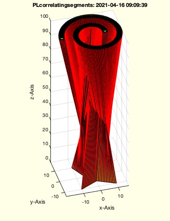 | % PLcorrelatingsegments(CPLA,CPLB,ww) - A new implemenation of PLcorrelate % (by Tim Lueth, VLFL-Lib, 2021-APR-15 as class: CLOSED POLYGON LISTS) % % This is a bug free version that stops automatically and ich double % checked by PLcorrelationcheck. May not optimal in all cases, but in % addition with FLofPLcorrelation and VLFLoptimizeFLWez a more reliable % base than the older concepts such as PLcorrelate or SGof2CPLz. Will see % It till creates self intruding facets, since it is not clear to me % wether there is alwas a possible solution in case of two planar contour. % (Status of: 2021-04-16) % % Introduced first in SolidGeometry 5.1 % % See also: PLplotcorrelation, PLdecompose, FLofPLcorrelation, % VLFLoptimizeFLWez % % CL=PLcorrelatingsegments(CPLA,CPLB,[ww]) % === INPUT PARAMETERS === % CPLA: Contour A, No NAN allowed % CPLB: Contour B, No NAN allowed % ww: angle resolution for PLdecompose default is pi/10 % === OUTPUT RESULTS ====== % CL: Ccrrelation list % % EXAMPLE: % PLcorrelatingsegments(CPLsample(3),CPLsample(6),pi/100); % PLcorrelatingsegments(CPLaddauxpoints(CPLsample(3),1),CPLaddauxpoints(CPLsample(20),pi/6)); % % See also: PLplotcorrelation, PLdecompose, FLofPLcorrelation, % VLFLoptimizeFLWez % % % Copyright 2021 Tim C. Lueth |
ismonotonously(x,circ)- returns wether a sequence in monotonously increasing or decreasing |
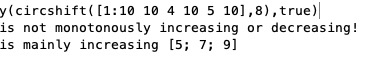 | // ismonotonously(x,circ) - returns wether a sequence in monotonously increasing or decreasing // (by Tim Lueth, VLFL-Lib, 2021-APR-14 as class: AUXILIARY PROCEDURES) // // Introduced first in SolidGeometry 5.1 // // See also: mod1circsequ // // [mon,fd,k]=ismonotonously(x,[circ]) // === INPUT PARAMETERS === // x: sequence [n x 1] or [1 x n] // circ: if true; x is a circular sequence with one jump; default is false // === OUTPUT RESULTS ====== // mon: 1= icreasing -1 => decreasing 0 == not monotonously // fd: indices of the faulty values // k: -1 = mainly decreasing, +1 = mainly increasing // // EXAMPLE: // ismonotonously(circshift([1:10 10 4 10 5 10],8),true) // // See also: mod1circsequ // // // Copyright 2021 Tim C. Lueth // |
PLsetdiff(CPL,PL,tol)- more tolerant than setdiff for vectors |
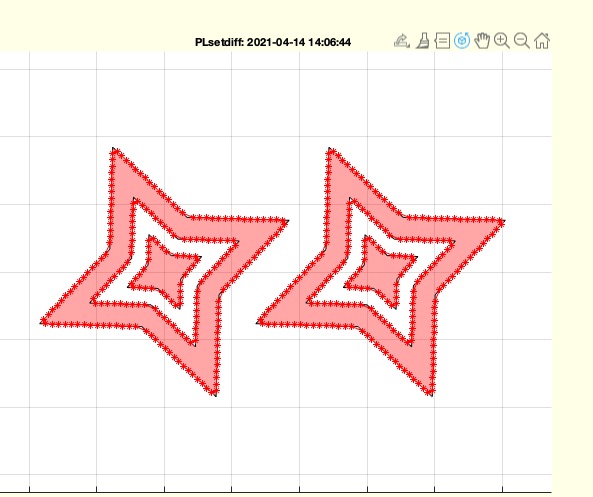 | % PLsetdiff(CPL,PL,tol) - more tolerant than setdiff for vectors % (by Tim Lueth, VLFL-Lib, 2021-APR-13 as class: CLOSED POLYGON LISTS) % % Introduced first in SolidGeometry 5.1 % % See also: setdiff % % PLN=PLsetdiff(CPL,PL,[tol]) % === INPUT PARAMETERS === % CPL: Point list A % PL: Point list B % tol: Tolerance % === OUTPUT RESULTS ====== % PLN: Returns a Point list CPL without PL % % EXAMPLE: % CPLsample(9); CPLA=ans; PLsetdiff(CPLA,[CPLA(3,:); CPLA(end-3,:)]); CPLB=ans % CPLinsertPL(CPLB,[CPLA(3,:);CPLA(end-3,:)]) % % See also: setdiff % % % Copyright 2021 Tim C. Lueth |
SGofCPLzfillgaphull(CPLA,z,bf,dn)- extrudes several regions without subregions into one region |
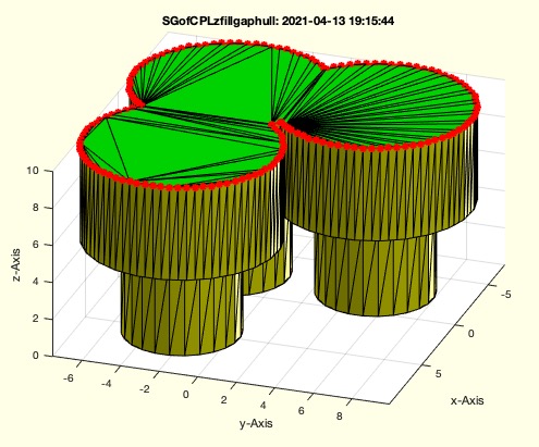 | % SGofCPLzfillgaphull(CPLA,z,bf,dn) - extrudes several regions without subregions into one region % (by Tim Lueth, VLFL-Lib, 2021-APR-13 as class: SURFACES) % % developed to improve SGof2CPLbranch (Status of: 2021-04-13) % % Introduced first in SolidGeometry 5.1 % % See also: SGof2CPLzfillgaphull % % [SG,FLXW,FLXA,FLXB,CVL2]=SGofCPLzfillgaphull(CPLA,[z,bf,dn]) % === INPUT PARAMETERS === % CPLA: Original Contour consisting of several regions without subregions % z: height to extrude % bf: buffer around CPLA used for CPLconvexhulloutline - fillgap % % dn: optional auxiliary point distance for single contour at top % === OUTPUT RESULTS ====== % SG: Solid Geometry VL/FL % FLXW: Just Wall with respect to SG.VL % FLXA: Just Floor with respect to SG.VL % FLXB: Just Ceiling with respect to SG.VL % CVL2: Top Contour % % EXAMPLE: % SGofCPLzfillgaphull(CPLsample(9) % SGofCPLzfillgaphull(CPLsample(41),10,2,0.5) % % See also: SGof2CPLzfillgaphull % % % Copyright 2021 Tim C. Lueth |
CPLinsertPL(CPL,PL,tol)- inserts removed points if they are on still exisiting lines |
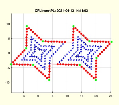 | % CPLinsertPL(CPL,PL,tol) - inserts removed points if they are on still exisiting lines % (by Tim Lueth, VLFL-Lib, 2021-APR-13 as class: CLOSED POLYGON LISTS) % % Sincy polyshape 'keeplinear' doe not work correctly, this fnctn was % programmed, to insert missing points afterwards of matlabfnctn % Even fnctns such as CPLbuffer suffers from that % % fnctn uses PLcrossCPLline not mirroringatline % (Status of: 2021-04-13) % % Introduced first in SolidGeometry 5.1 % % See also: PLcrossCPLline % % CPLN=CPLinsertPL(CPL,PL,[tol]) % === INPUT PARAMETERS === % CPL: arbitrary CPL % PL: unosrted list of points that may be on lines of CPL % tol: maximum distance % === OUTPUT RESULTS ====== % CPLN: New CPL with inserted Points if possible % % EXAMPLE: % CPLX=CPLaddauxpoints(CPLsample(14),1); % CPLfillgap(CPLX,3,'miter',true); CPLN=ans; % CPLinsertPL(CPLN,CPLX); % LOST % CPLinsertPL(CPLX,CPLN); % CHANGES TO ORIGINAL % CPLfillgap(CPLX,3,'miter',false); CPLN=ans; % CPLinsertPL(CPLN,CPLX); % % % See also: PLcrossCPLline % % % Copyright 2021 Tim C. Lueth |
bugexp_2021_04_13_PLcorrelate- EXPERIMENT to show a problematic Solid Design from 2 multi region CPLS |
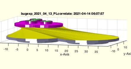 | % bugexp_2021_04_13_PLcorrelate - EXPERIMENT to show a problematic Solid Design from 2 multi region CPLS % (by Tim Lueth, VLFL-Lib, 2021-APR-13 as class: EXPERIMENTS) % % While the transition 1:n or n:1 with the fnctn SGofCPLzfillgaphull has % been redesigned compared to SGof2CPLzbranch, the problem of assigning % the point of two contours of which at least one has strongly curved and % direction-changing contour segments remains.Possibly CPLdecomponse must % be used or the segments must be optimized locally afterwards. (Status % of: 2021-04-14) % % Introduced first in SolidGeometry 5.1 % % See also: SGof2CPLzfillgaphull % % bugexp_2021_04_13_PLcorrelate % % See also: SGof2CPLzfillgaphull % % % Copyright 2021 Tim C. Lueth |
CVLzcut(CVL,z)- cuts out defined z levels |
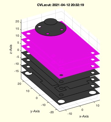 | % CVLzcut(CVL,z) - cuts out defined z levels % (by Tim Lueth, VLFL-Lib, 2021-APR-10 as class: CLOSED POLYGON LISTS) % % ATTENTION: OUTPUT ORDER IS DIFFERENT TO SGcut ! (Status of: 2021-04-12) % % Introduced first in SolidGeometry 5.1 % % See also: CVLzflipud, CVLzplot, CVLzplotasCPS, CVLzplotui % % [CVLA,CVLB]=CVLzcut(CVL,[z]) % === INPUT PARAMETERS === % CVL: Original CVLz % z: [z1] for z1..top or [z1 z2] for z1..z2 % === OUTPUT RESULTS ====== % CVLA: Upper Part or niddle part % CVLB: Lower Part and Upper part % % EXAMPLE: % CVLzcut(CVLzsample(2),[0 15]) % % See also: CVLzflipud, CVLzplot, CVLzplotasCPS, CVLzplotui % % % Copyright 2021 Tim C. Lueth |
SGof2facets (w1,w2,w3)- creates a surface consisting of two faces |
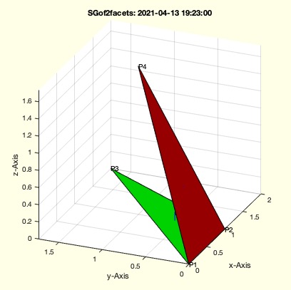 | % SGof2facets (w1,w2,w3) - creates a surface consisting of two faces % (by Tim Lueth, VLFL-Lib, 2021-APR-10 as class: SURFACES) % % In this example the second triangle is rotated using the edge as % rotation matrix. (Status of: 2021-04-13) % % Introduced first in SolidGeometry 5.1 % % See also: mirroringatline3D % % SGof2facets([w1,w2,w3]) % === INPUT PARAMETERS === % w1: [angle 1 length 1] % w2: [angle 2 length 2] % w3: angle rotation agains axis % % EXAMPLE: % SGof2facets(pi/3,pi/2,pi/3) % % See also: mirroringatline3D % % % Copyright 2021 Tim C. Lueth |
VLFLfaceneighborhood(VL,FL,fi,n)- return the neighbors and the neighbor neighbors |
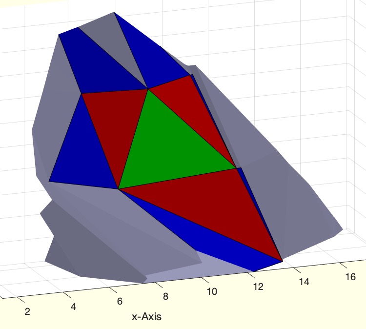 | % VLFLfaceneighborhood(VL,FL,fi,n) - return the neighbors and the neighbor neighbors % (by Tim Lueth, VLFL-Lib, 2021-APR-10 as class: SURFACES) % % Introduced first in SolidGeometry 5.1 % % See also: VLFLfaceneighborangle % % fil=VLFLfaceneighborhood(VL,FL,fi,n) % === INPUT PARAMETERS === % VL: Vertex list % FL: Facet list % fi: face index % n: shells of neighbors % === OUTPUT RESULTS ====== % fil: cell list of neighborhood % % EXAMPLE: % load JACO_robot.mat % or loadweb % VLFLfaceneighborhood(JC1.VL,JC1.FL,11181,10) % VLFLfaceneighborhood(SGsphere(1),'',100,2) % % See also: VLFLfaceneighborangle % % % Copyright 2021 Tim C. Lueth |
dbsave(var2base)- writes for debugging variables into the global workspace |
 | % dbsave(var2base) - writes for debugging variables into the global workspace % (by Tim Lueth, VLFL-Lib, 2021-APR-10 as class: LANGUAGE PROCEDURES) % % A fnctn, MathWorks should implement for quick debugging. Same % fnctnality also implemented for dbreturn. % By using dbprintmode, it is possible to ectivate the openinline fnctn % to reach the fnctn call immedeatly (Status of: 2021-11-02) % % Introduced first in SolidGeometry 5.1 % % See also: dbprintf, dbreturn, dbexit, dbprintmode % % dbsave([var2base]) % === INPUT PARAMETERS === % var2base: list of variables that should be in the workspace after return % % EXAMPLE: works only in funct % testvar=4; % dbsave(testvar); % creates testvar in workspace % % % See also: dbprintf, dbreturn, dbexit, dbprintmode % % % Copyright 2021 Tim C. Lueth |
VLFLfaceneighborangle(VL,FLi,FLn)- returns a signed (convex/concave) normal vector difference |
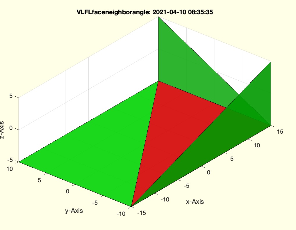 | % VLFLfaceneighborangle(VL,FLi,FLn) - returns a signed (convex/concave) normal vector difference % (by Tim Lueth, VLFL-Lib, 2021-APR-09 as class: ANALYTICAL GEOMETRY) % % used in VLFLremovekinks % positive angle is concave % negative angle is convex (Status of: 2021-04-09) % % Introduced first in SolidGeometry 5.1 % % See also: VLFLremovekinks % % w=VLFLfaceneighborangle(VL,FLi,FLn) % === INPUT PARAMETERS === % VL: Vertex list % FLi: single face row % FLn: up to 3 rows for neighbor facets % === OUTPUT RESULTS ====== % w: angles related to the FLn % % EXAMPLE: % A=SGbox; % VLFLfaceneighborangle(A.VL,A.FL(1,:),A.FL([2 5 10 ],:)) % % See also: VLFLremovekinks % % % Copyright 2021 Tim C. Lueth |
VLFLfaceneighborswapangle(VL,FL,fi,k,NN,w,A)- returns and explains swapping decisions |
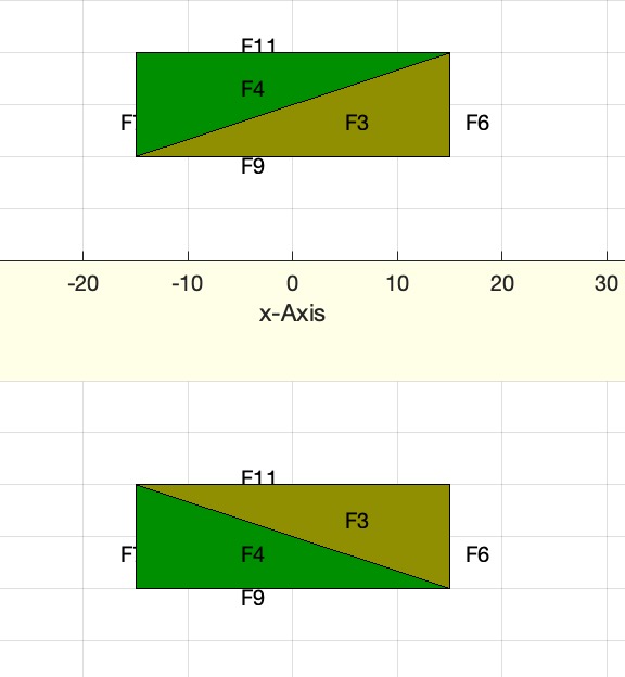 | % VLFLfaceneighborswapangle(VL,FL,fi,k,NN,w,A) - returns and explains swapping decisions % (by Tim Lueth, VLFL-Lib, 2021-APR-09 as class: ANALYTICAL GEOMETRY) % % educational fnctn for removing kinks % similar to VLFLfaceneighborswap (Status of: 2021-04-10) % % Introduced first in SolidGeometry 5.1 % % See also: VLFLtrianglegeometry, VLFLfaceneighborswap % % [www,ci,i4]=VLFLfaceneighborswapangle(VL,FL,fi,[k,NN,w,A]) % === INPUT PARAMETERS === % VL: Vertex List % FL: Facet List % fi: face index to swap % k: index (1..3) to swap % NN: seeVLFLtrianglegeometry % w: see VLFLtrianglegeometry % A: see VLFLtrianglegeometry % === OUTPUT RESULTS ====== % www: angle information % ci: used neigbor to fi == NN(fi,k) % i4: vertex index for new triangles % % EXAMPLE: % SG=SGbox; % VLFLfaceneighborswapangle(SG.VL,SG.FL,1) % VLFLfaceneighborswapangle(SG.VL,SG.FL,1,3) % % See also: VLFLtrianglegeometry, VLFLfaceneighborswap % % % Copyright 2021 Tim C. Lueth |
VLFLfaceneighborswap(VL,FL,fi,k)- shows what happens if a triangle-pair is swapped |
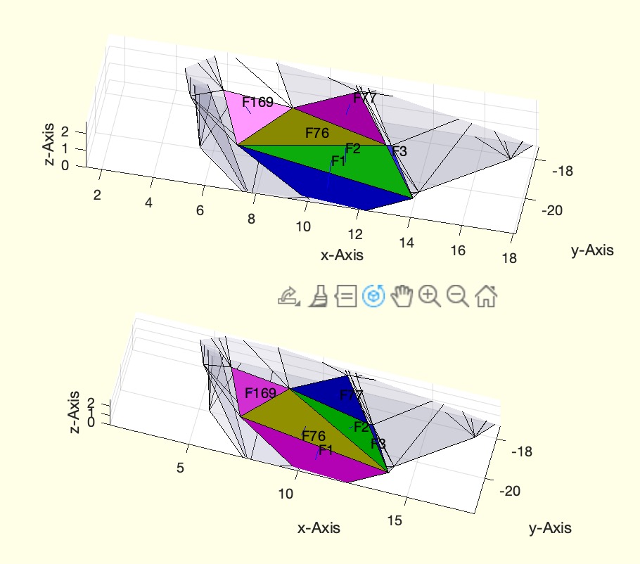 | % VLFLfaceneighborswap(VL,FL,fi,k) - shows what happens if a triangle-pair is swapped % (by Tim Lueth, VLFL-Lib, 2021-APR-09 as class: SURFACES) % % educational fnctn, explaining coding % written in Grindelwald (Status of: 2021-04-09) % % Introduced first in SolidGeometry 5.1 % % See also: VLFLremovelargeangle % % VLFLfaceneighborswap(VL,FL,fi,k) % === INPUT PARAMETERS === % VL: Vertex list % FL: Facet list % fi: face index % k: number of neigbor (1..3) % % See also: VLFLremovelargeangle % % % Copyright 2021 Tim C. Lueth |
VLFLtrianglegeometry(VL,FL,fi)- returns all important information on the triangles of a facet list |
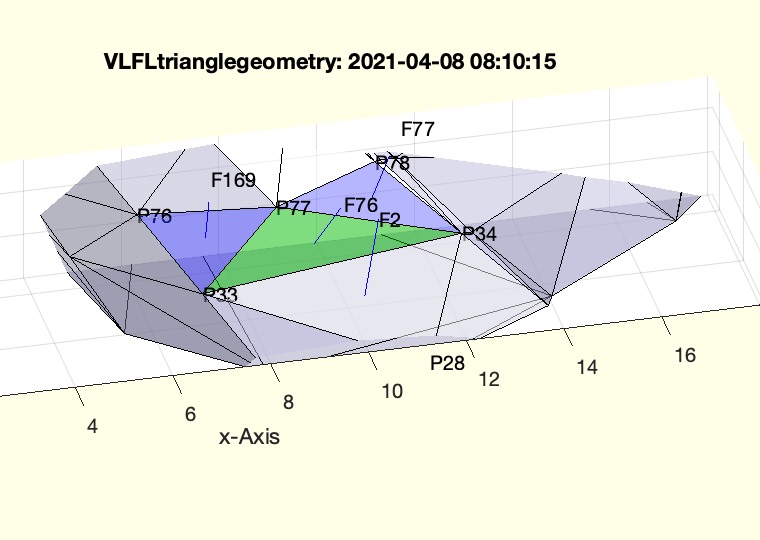 | % VLFLtrianglegeometry(VL,FL,fi) - returns all important information on the triangles of a facet list % (by Tim Lueth, VLFL-Lib, 2021-APR-07 as class: ANALYZING PROCEDURES) % % precalculation fnctn % Call once to analyze meshes afterwards (Status of: 2021-04-09) % % Introduced first in SolidGeometry 5.1 % % See also: SGchecktrianglegeometry, VLFLremovelargeangle, % VLFLfaceAngles, VLFLfaceNormal % % [w,d,A,NL,NN]=VLFLtrianglegeometry([VL,FL,fi]) % === INPUT PARAMETERS === % VL: Vertex list % FL: Facet list [1 2 3; etc % fi: face index; makes sense only if there is no output % === OUTPUT RESULTS ====== % w: angle [w1 w2 w3] wrt. [v1 v2 v3] % d: length [d1 d2 d3] wrt. opponent edge to [v1 v2 v3] % A: area of triangle % NL: Normal vector of facets % NN: Neigbor of facet wrt. opponent edge to [v1 v2 v3] % % EXAMPLE: % VLX=[4 4; 10 0; 0 10; 7 6; 0 0; 10 10]; % FLX=[4 3 1; 3 5 1; 4 6 3; 5 2 1; 2 6 4; 1 2 4]; % % VLFLtrianglegeometry(VLX,FLX) % % % See also: SGchecktrianglegeometry, VLFLremovelargeangle, % VLFLfaceAngles, VLFLfaceNormal % % % Copyright 2021 Tim C. Lueth |
VLFLremovekinks(VL,FL,re)- removes kinks after SGofCVLz |
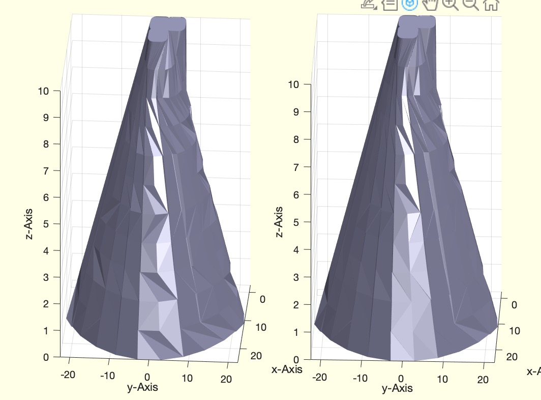 | % VLFLremovekinks(VL,FL,re) - removes kinks after SGofCVLz % (by Tim Lueth, VLFL-Lib, 2021-APR-07 as class: SURFACES) % % slow, and not perfect recursive fnctn % not completely understood (Status of: 2021-04-08) % % Introduced first in SolidGeometry 5.1 % % See also: VLFLfaceneighborangle % % [SGN,cnt]=VLFLremovekinks([VL,FL,re]) % === INPUT PARAMETERS === % VL: Vertexn list % FL: Facet list % re: recursion; default is true % === OUTPUT RESULTS ====== % SGN: New Sold % cnt: number of changes % % See also: VLFLfaceneighborangle % % % Copyright 2021 Tim C. Lueth |
editorwindow- opens the last file modified file in the editor window |
 | % editorwindow - opens the last file modified file in the editor window % (by Tim Lueth, VLFL-Lib, 2021-APR-07 as class: USER INTERFACE) % % Introduced first in SolidGeometry 5.1 % % See also: openbydoubleclick, matlabopen, commandwindow, shg % % editorwindow % % See also: openbydoubleclick, matlabopen, commandwindow, shg % % % Copyright 2021-2022 Tim C. Lueth |
camofVLFLfi(VL,FL,fi,gf)- shows to a specific facet for inspecting a facet of interest |
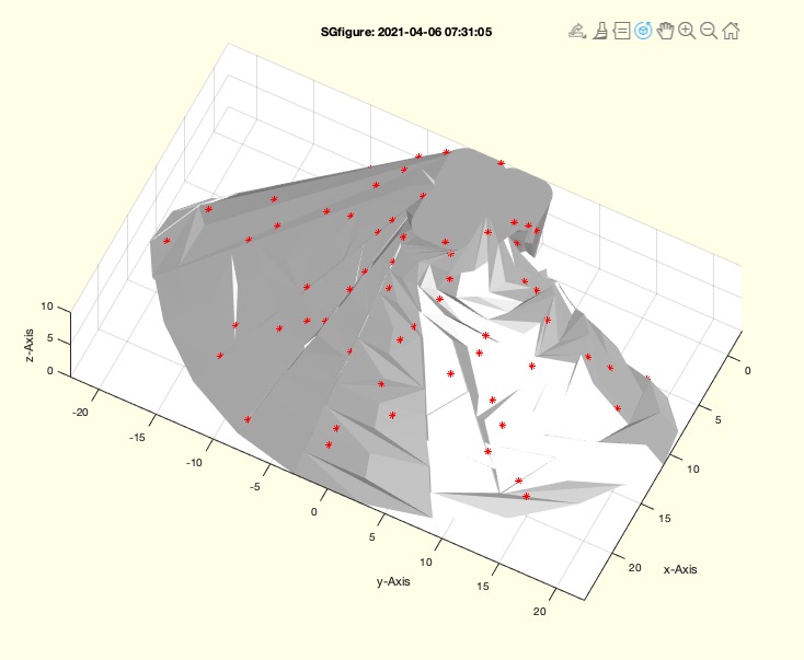 | % camofVLFLfi(VL,FL,fi,gf) - shows to a specific facet for inspecting a facet of interest % (by Tim Lueth, VLFL-Lib, 2021-APR-06 as class: VISUALIZATION) % % Introduced first in SolidGeometry 5.1 % % See also: camofT, VLFLplotfi, plotVLFLfi % % camofVLFLfi(VL,FL,[fi,gf]) % === INPUT PARAMETERS === % VL: Vertex list % FL: Facet list % fi: facet % gf: grow arund factor; default is 10 % % EXAMPLE: % SGsphere(10); SG=ans; camofVLFLfi(SG.VL,SG.FL,1000) % SGsphere(10); SG=ans; camofVLFLfi(SG.VL,SG.FL,1000,30) % % See also: camofT, VLFLplotfi, plotVLFLfi % % % Copyright 2021 Tim C. Lueth |
CPLdullededges(CPL,d,typ)- returns a CPL with dulled edges |
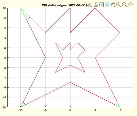 | % CPLdullededges(CPL,d,typ) - returns a CPL with dulled edges % (by Tim Lueth, VLFL-Lib, 2021-APR-05 as class: CLOSED POLYGON LISTS) % % makes sense after CPLtransform (Status of: 2021-04-05) % % Introduced first in SolidGeometry 5.1 % % See also: CPLbuffer, CPLradialEdges % % CPLN=CPLdullededges(CPL,[d,typ]) % === INPUT PARAMETERS === % CPL: CPL % d: distance between edges % typ: miter (sharp edges) or square (alle egdes) or round (all edges)l % default is miter % === OUTPUT RESULTS ====== % CPLN: New CPL % % EXAMPLE: % CPLdullededges(CPLsample(7)) % % See also: CPLbuffer, CPLradialEdges % % % Copyright 2021 Tim C. Lueth |
SGrotate4print(SG,ez,st)- rotates an object to achieve as long as possible lines on the floot |
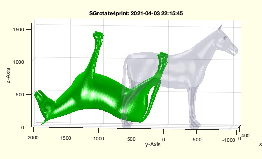 | % SGrotate4print(SG,ez,st) - rotates an object to achieve as long as possible lines on the floot % (by Tim Lueth, VLFL-Lib, 2021-APR-03 as class: ANALYTICAL GEOMETRY) % % developed for Luisa and Julia Prinz, Dietersheim (Status of: 2021-04-03) % % Introduced first in SolidGeometry 5.1 % % See also: SGrotate % % SGN=SGrotate4print(SG,[ez,st]) % === INPUT PARAMETERS === % SG: Soli Geometry % ez: direction of the base plate; default is [0 0 1] % st: number of auxiliary grid points; default is at least 3 % === OUTPUT RESULTS ====== % SGN: Rotated Geoemtry % % % EXAMPLE: % SGrotate4print(Horse,'+z'); SGN=ans % % See also: SGrotate % % % Copyright 2021 Tim C. Lueth |
mod1circsequ(s,e,n)- returns a forwared sequence from start to end and a backward sequence from start to end |
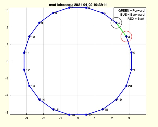 | % mod1circsequ(s,e,n) - returns a forwared sequence from start to end and a backward sequence from start to end % (by Tim Lueth, VLFL-Lib, 2021-APR-02 as class: AUXILIARY PROCEDURES) % % Introduced first in SolidGeometry 5.1 % % See also: VLpathdist, mod1 % % [forw,back]=mod1circsequ(s,e,n) % === INPUT PARAMETERS === % s: start point % e: end point % n: number of points % === OUTPUT RESULTS ====== % forw: [s .. e] always increasing numbers % back: [s .. e] always decreasing numbers % % EXAMPLE: % mod1circsequ(3,10,20); % mod1circsequ(10,3,20); % % See also: VLpathdist, mod1 % % % Copyright 2021 Tim C. Lueth |
getkeyboardchartimer(chrset,maxtime)- fnct getkey for figures if rotate3d is on - and the callbacks are blocked |
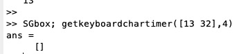 | % getkeyboardchartimer(chrset,maxtime) - fnct getkey for figures if rotate3d is on - and the callbacks are blocked % (by Tim Lueth, VLFL-Lib, 2021-APR-02 as class: USER INTERFACE) % % Improved version of getkeyboardcharpause - Shows also some second % waiting text % % In Matlab there are different possibilities to get a char from the % keyboard if a figure is open. The method depends on the rotate3d mode. % If rotate3d is on, mouse buttons and keyboard are blocked for % callbacks ==> The pause command must be used in combination with % get(gcf,'CurrentCharacter'). If rotate3d is on, a callback fnctn can be % used to detect mouse buttons and keyboard chars. Also ginput(1) can be % used (Status of: 2021-08-11) % % Introduced first in SolidGeometry 5.1 % % See also: ginput, getkeyboardcharpause, waitforfigurekeyboardchar % % c=getkeyboardchartimer([chrset,maxtime]) % === INPUT PARAMETERS === % chrset: set of allowed character; default is 1:255 % maxtime: maximum of waiting time; default is 3 seconds % === OUTPUT RESULTS ====== % c: uint8 of char pressed during pause command and rotate3d was on % % EXAMPLE: % SGbox; getkeyboardchartimer('',4) % returns the pressed key or stops after 4 seconds % % See also: ginput, getkeyboardcharpause, waitforfigurekeyboardchar % % % Copyright 2021 Tim C. Lueth |
VLpathdist(VLD,i,k)- distance between two points on a CVP PAth |
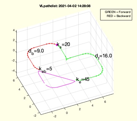 | % VLpathdist(VLD,i,k) - distance between two points on a CVP PAth % (by Tim Lueth, VLFL-Lib, 2021-APR-01 as class: CLOSED POLYGON LISTS) % % to speed up calc VLD before (Status of: 2021-04-01) % % Introduced first in SolidGeometry 5.1 % % See also: VLdistance, mod1circsequ % % lll=VLpathdist(VLD,i,k) % === INPUT PARAMETERS === % VLD: VLdistance(CVL) or CVL % i: start index % k: end index; if more than 1 index, the shortes forward and the % shortest backward is selected % === OUTPUT RESULTS ====== % lll: forward distance-backward-distance overall-length]; two rows in % numel(k)>1 % % EXAMPLE: % VLpathdist (CPLsample(20),20,50) % CLD=VLdistance(CPLsample(3)), VLpathdist (CLD,2,8), % graphics output uses a circle % VLpathdist(CPLsample(3),2,8) % VLpathdist (CPLsample(40),20,[45 5]) % % See also: VLdistance, mod1circsequ % % % Copyright 2021 Tim C. Lueth |
isCVP(VL)- returns wether a sequence of vertices is a contour vertex path |
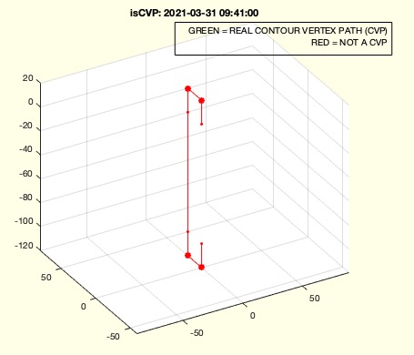 | % isCVP(VL) - returns wether a sequence of vertices is a contour vertex path % (by Tim Lueth, VLFL-Lib, 2021-MÄR-31 as class: CLOSED POLYGON LISTS) % % OPEN % SINGLE 3D LINE % NOT ANGLE LARGER THAN 45 DEGREE (Status of: 2021-03-31) % % Introduced first in SolidGeometry 5.1 % % See also: CVLpathwarning, VLof2TR % % x=isCVP(VL) % === INPUT PARAMETERS === % VL: Vertex list % === OUTPUT RESULTS ====== % x: true if all conditions are fullfilled % % EXAMPLE: % TLofn([1 6 6]); TL=ans; VLof2TR(TL(:,:,1),TL(:,:,2),10); VL=ans; isCVP((VL)) % TLofn([1 6 6]);TL=ans; VLof2TR(TL(:,:,1),TL(:,:,2),10); VL=ans; isCVP(VLradialEdges(VL,5)) % % See also: CVLpathwarning, VLof2TR % % % Copyright 2021 Tim C. Lueth |
RLofCVL(CVL,res)- Returns Radii of a contour, same as CVLdimclassifier |
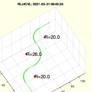 | % RLofCVL(CVL,res) - Returns Radii of a contour, same as CVLdimclassifier % (by Tim Lueth, VLFL-Lib, 2021-MÄR-31 as class: CLOSED POLYGON LISTS) % % % RL=[cx cy cz Nr deg R vx vy vz] (Status of: 2021-03-31) % % Introduced first in SolidGeometry 5.1 % % See also: CVLdimclassifier % % [RL,RMM]=RLofCVL(CVL,[res]) % === INPUT PARAMETERS === % CVL: 3D path in space % res: default is 0.1 % === OUTPUT RESULTS ====== % RL: [cx cy cz Nr deg R vx vy vz] % RMM: [rmin rmax] % % EXAMPLE: % CVL=VLofT(TLof2T(TLofn(0))); RLofCVL(CVL) % RLofCVL (CVL) % CVL=VLofT(TLof2T(TLofn(0),'','',20)); RLofCVL(CVL) % % % See also: CVLdimclassifier % % % Copyright 2021 Tim C. Lueth |
CVLzflipud(CVLz)- flips z values for a CVLz |
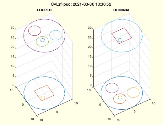 | % CVLzflipud(CVLz) - flips z values for a CVLz % (by Tim Lueth, VLFL-Lib, 2021-MÄR-30 as class: CLOSED POLYGON LISTS) % % THE ORIENTATION cw/ccw will not change by changing z values (Status of: % 2021-03-31) % % Introduced first in SolidGeometry 5.1 % % See also: CVLzsample % % CVLn=CVLzflipud(CVLz) % === INPUT PARAMETERS === % CVLz: Original CVLz % === OUTPUT RESULTS ====== % CVLn: CVLZ up and down % % EXAMPLE: % CVLzflipud(CVLzsample); % % See also: CVLzsample % % % Copyright 2021 Tim C. Lueth |
CVLzisccwcorrected(CVLz,keepcolinear,simplify)- corrects cw/ccw orientation and removes doubled start/end points |
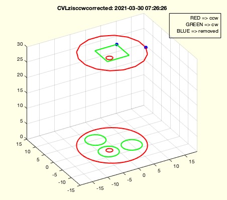 | % CVLzisccwcorrected(CVLz,keepcolinear,simplify) - corrects cw/ccw orientation and removes doubled start/end points % (by Tim Lueth, VLFL-Lib, 2021-MÄR-30 as class: CLOSED POLYGON LISTS) % % Introduced first in SolidGeometry 5.1 % % See also: CPLisccwcorrectedCPS % % CVLz=CVLzisccwcorrected(CVLz,[keepcolinear,simplify]) % === INPUT PARAMETERS === % CVLz: List of planar CPLs with % keepcolinear: default is true % simplify: default is true | NEVER CHANGE TO FALSE! % === OUTPUT RESULTS ====== % CVLz: New CVLz in right order and % % EXAMPLE: % tic; CVLzisccwcorrected(CVLzsample); toc % tic; CVLzisccwcorrected(CVLzaddauxpoints(CVLzsample,1),true); toc % tic; CVLzisccwcorrected(CVLzaddauxpoints(CVLzsample,1),false); toc % % See also: CPLisccwcorrectedCPS % % % Copyright 2021 Tim C. Lueth |
CVLzsample(Nr,T)- creates a CVLz sample for different Purposes |
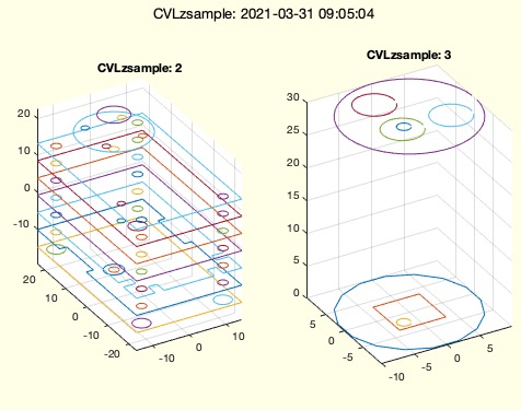 | % CVLzsample(Nr,T) - creates a CVLz sample for different Purposes % (by Tim Lueth, VLFL-Lib, 2021-MÄR-30 as class: CLOSED POLYGON LISTS) % % Introduced first in SolidGeometry 5.1 % % See also: VLsampletriangles, CPLsample, SGsample, VLsample, PLsample, % VLFLsample, CSGsample % % CVLz=CVLzsample([Nr,T]) % === INPUT PARAMETERS === % Nr: Number of % T: optional Parameter to Transform CVLz % === OUTPUT RESULTS ====== % CVLz: Set of planar CPLS' in different z levels % % See also: VLsampletriangles, CPLsample, SGsample, VLsample, PLsample, % VLFLsample, CSGsample % % % Copyright 2021 Tim C. Lueth |
T2ofCVLpath(XVL,T1,T2)- Returns Start frame and End Frame for a Contour path |
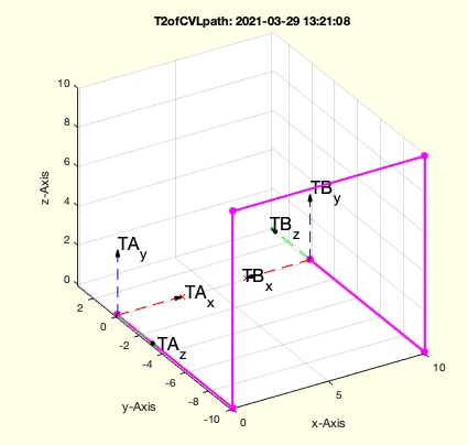 | % T2ofCVLpath(XVL,T1,T2) - Returns Start frame and End Frame for a Contour path % (by Tim Lueth, VLFL-Lib, 2021-MÄR-29 as class: KINEMATICS AND FRAMES) % % In order to generate correct frame sequences for a contour path, angle % changes greater than or equal to 90 degrees must not be made under any % circumstances, since these changes or the possible Euler angles for % this are ambiguous. So it is absolutely necessary to round or break the % edges before converting the point sequence into a frame sequence. This % is done for example with the fnctns: VLradialEdges(XVL), VLBezierC(XVL) % or VLradialEdges(VLBezierC(XVL). % ------------------------ % For example, contour paths without predefined frames are created with % VLsample or also VLof2TR. These two fnctns provide the simplest % possible path skeleton with kinks and straight sections. In other % words, no correct frame sequences can be generated from it yet! % However, while with VLof2TR the start and end frames were already % known, these must be generated with VLsample first! % ------------------------ % THIS FNCTN T2ofCVLpath RETURNS the start frame and the end frame of a % contour path. These frames can be torsioned/twisted against each other % and the rotation dw specifies by which angle the torsion exists % ------------------------ % As soon as a path through broken or rounded corners has only angles < % 90 degrees [VLradialEdges(XVL), VLBezierC(XVL) or % VLradialEdges(VLBezierC(XVL) ] the torsion between start point and end % point is computable. This is done with VLedgeNormal. The start and end % frame can then be derived from this. % ------------------------ % If there is the wish that a contour has a certain rotation angle offset % at the start and at the end this can be achieved with the fnctn % TLadjustR. However, this also only makes sense if it is already ensured % that no corner with angle >=90 degrees occurs. % ------------------------ % The fnctn TLofCVL has been modified to support old an new concepts. % OLD Concept: % CVLof2T % % NEW Concept: TLof2T replacing VLradialEdges2T one day % 2 Frames (TLofn) arbitray two frames TA and TB in space % =>Frame skeleton(VLof2TR) Path skeletons with 90 degree angles % =>Broken edges(VLradialEdges) Path with no angle >= 90 degree % =>Frame list(T2ofCVLpath) Full frame list of % =>Adjusted Torsion(TLadjustR) Adjusted Torsion to start with TA and end % With TB (Status of: 2021-03-29) % % Introduced first in SolidGeometry 5.1 % % See also: VLsample, VLof2TR % % [TL,dw,Ti]=T2ofCVLpath(XVL,[T1,T2]) % === INPUT PARAMETERS === % XVL: Simple Contour Path % T1: Only if T1 and T2 are known already => calls Ti=TLadjustR(Ti,T1,T2); % T2: Only if T1 and T2 are known already => calls Ti=TLadjustR(Ti,T1,T2); % === OUTPUT RESULTS ====== % TL: Inside Start-Frame and Outside End-Frame % dw: angle difference [torsion inclination] in rad % Ti: Full List of Frames % % EXAMPLE: % T2ofCVLpath(VLsample(9)) % Not Torsion, Inclination 90 degree % T2ofCVLpath(VLsample(14)) % Correct but dw is correct more by chance % T2ofCVLpath(VLradialEdges(VLsample(14),2)) % Correct and dw is definitely reliable % % See also: VLsample, VLof2TR % % % Copyright 2021 Tim C. Lueth |
CVLpathwarning(CVL,warna,ignor)- warns if a path contains angles larger than pi/2 |
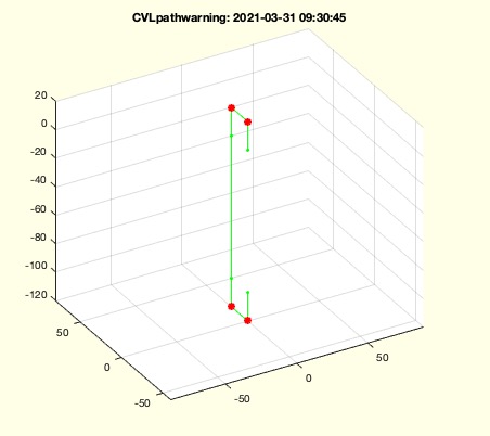 | % CVLpathwarning(CVL,warna,ignor) - warns if a path contains angles larger than pi/2 % (by Tim Lueth, VLFL-Lib, 2021-MÄR-29 as class: CLOSED POLYGON LISTS) % % Introduced first in SolidGeometry 5.1 % % See also: isCVP, VLof2TR % % wa=CVLpathwarning(CVL,[warna,ignor]) % === INPUT PARAMETERS === % CVL: % warna: warning angle; default is pi/2*0.99 % ignor: if true (default), CvL is considered as open, if false start to % end is also considered % === OUTPUT RESULTS ====== % wa: true if angles exist larger thatn pi/2 % % EXAMPLE: % TLofn([1 6 6]);TL=ans; VLof2TR(TL(:,:,1),TL(:,:,2),10); VL=ans; CVLpathwarning(VL) % TLofn([1 6 6]);TL=ans; VLof2TR(TL(:,:,1),TL(:,:,2),10); VL=ans; CVLpathwarning(VLradialEdges(VL,5)) % % See also: isCVP, VLof2TR % % % Copyright 2021 Tim C. Lueth |
VLof2TR(TA,TB,R,ty);- returns a path with minimal number of axuiliary points to come from frame A to Frame B |
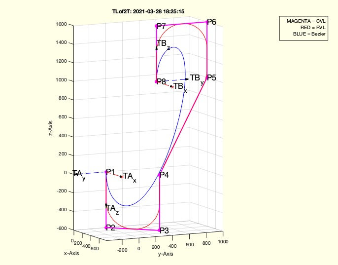 | % VLof2TR(TA,TB,R,ty); - returns a path with minimal number of axuiliary points to come from frame A to Frame B % (by Tim Lueth, VLFL-Lib, 2021-MÄR-28 as class: KINEMATICS AND FRAMES) % % New version of CVLof2T, uses VLofTtoP % RVL=VLradialEdges(CVL,R); % BVL=VLBezierC(CVL,100); % create smoother contours if used afterwards % (Status of: 2021-03-31) % % Introduced first in SolidGeometry 5.1 % % See also: VLofTtoP, VLradialEdges, VLBezierC, TLof2T, CVLpathwarning % % [CVL,RVL]=VLof2TR([TA,TB,R,ty]); % === INPUT PARAMETERS === % TA: Frame A, z-vector shows forward creating the start of the path % TB: Frame B, z-vector shows backwards creating the end of the path % R: Minimal Radius % ty: not supported yet, default is 'skeleton' => CVLpathwarning % === OUTPUT RESULTS ====== % CVL: List of 2 to 4 points % RVL: List with more points to create a radial path % % EXAMPLE: % TLofn([1 6],'','',100); TL=ans; % Distance 100 % VLof2TR(TL(:,:,1),TL(:,:,2),10) % Radius 10 % % See also: VLofTtoP, VLradialEdges, VLBezierC, TLof2T, CVLpathwarning % % % Copyright 2021 Tim C. Lueth |
VLofTtoP(TA,PB,R)- returns a list o fpoints that create a shortes path towards PB with radius R |
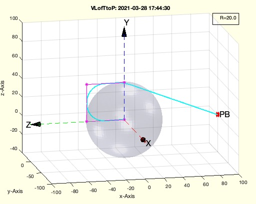 | % VLofTtoP(TA,PB,R) - returns a list o fpoints that create a shortes path towards PB with radius R % (by Tim Lueth, VLFL-Lib, 2021-MÄR-28 as class: KINEMATICS AND FRAMES) % % PB is not included into CVL. This fnctn is used in VLof2T (Status of: % 2021-03-28) % % Introduced first in SolidGeometry 5.1 % % See also: VLof2TR % % CVL1=VLofTtoP([TA,PB,R]) % === INPUT PARAMETERS === % TA: Frame % PB: Final point to reach % R: minimal required radius % === OUTPUT RESULTS ====== % CVL1: List of 2 to 4 points starts at TA leads towards PB % % EXAMPLE: % VLofTtoP(Tofn(0,[1 4 5]),[50 50 50]) % VLofTtoP(Tofn(0),'',20) % x=VLofTtoP(Tofn(0,[1 4 5]),[50 50 50]) % % See also: VLof2TR % % % Copyright 2021 Tim C. Lueth |
TLofn(n,poff,woff,d)- returns a frame 1 of 36 with different ez vector and orientation |
 | % TLofn(n,poff,woff,d) - returns a frame 1 of 36 with different ez vector and orientation % (by Tim Lueth, VLFL-Lib, 2021-MÄR-27 as class: KINEMATICS AND FRAMES) % % Used for creating test cases; returns values for about 10000 simple but % different double frame cases (Status of: 2021-03-28) % % Introduced first in SolidGeometry 5.1 % % See also: Tofn, VLof2TR % % [T1,T2]=TLofn([n,poff,woff,d]) % === INPUT PARAMETERS === % n: 1..36 for an frame; if n==0 a random solution is selected % poff: offset value; default is [0 0 0] % woff: angle osset default is 0 % d: distance between the two frames default is 100 % === OUTPUT RESULTS ====== % T1: List of two frames or T1 % T2: T2 % % EXAMPLE: % TLofn(0) % [T1,T2]=TLofn(0,'',pi/5); TLof2T(T1,T2,0,10); % [T1,T2]=TLofn(1221,'',pi/5); TLof2T(T1,T2,0,10); % TL=TLofn(832); TLof2T(TL(:,:,1),TL(:,:,2),0,10); % % See also: Tofn, VLof2TR % % % Copyright 2021 Tim C. Lueth |
Tofn(n,poff,woff)- provides a standardized test frame from 1 of 36 with different ez-vector and orientation |
 | % Tofn(n,poff,woff) - provides a standardized test frame from 1 of 36 with different ez-vector and orientation % (by Tim Lueth, VLFL-Lib, 2021-MÄR-27 as class: KINEMATICS AND FRAMES) % % Used for creating test cases for instance for TLof2T (Status of: % 2021-03-28) % % Introduced first in SolidGeometry 5.1 % % See also: TLofn, VLof2TR % % Tofn([n,poff,woff]) % === INPUT PARAMETERS === % n: 1..36 for an frame; if n==0 a random solution is selected % poff: offset value; default is [0 0 0] % woff: angle osset default is 0 % % EXAMPLE: % Tofn(11) % Tofn('',[0 100 0], pi/10) % % See also: TLofn, VLof2TR % % % Copyright 2021 Tim C. Lueth |
CPLplotTL(CPL,TL,parameter)- silpmy plot a contour transferred wrt to list fo frames |
 | % CPLplotTL(CPL,TL,parameter) - silpmy plot a contour transferred wrt to list fo frames % (by Tim Lueth, VLFL-Lib, 2021-MÄR-27 as class: USER INTERFACE) % % Introduced first in SolidGeometry 5.1 % % See also: CPLplot % % h=CPLplotTL(CPL,TL,[parameter]) % === INPUT PARAMETERS === % CPL: 2D planar contour % TL: List of frames [4x4xn] % parameter: similar to PLplot % === OUTPUT RESULTS ====== % h: handle to plot % % EXAMPLE: % TA=eye(4); TB=TofR([0 pi/2 0],[0 0 40]); R=10; % CVLof2T(TA,TB,'',R,'radial'); CVL=ans; whos CVL % TLofCVL(CVL,R,TA,TB); TL=ans; % CPLplotTL(CPL,TL) % % % See also: CPLplot % % % Copyright 2021 Tim C. Lueth |
TLof2T(TA,TB,elo,Rv,Cs)- returns a list of Frames between a start frame and an end frame |
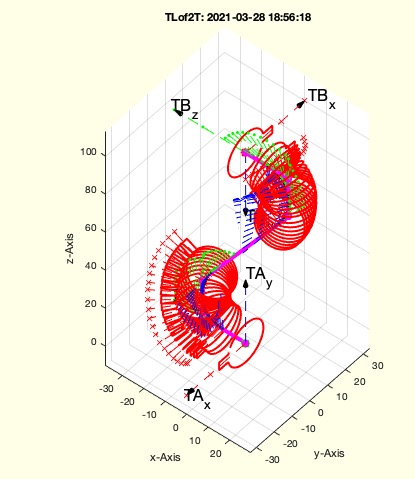 | % TLof2T(TA,TB,elo,Rv,Cs) - returns a list of Frames between a start frame and an end frame % (by Tim Lueth, VLFL-Lib, 2021-MÄR-27 as class: KINEMATICS AND FRAMES) % % This fnctn needs TLofn to be tested sufficiently % Some kind of tutorial fnctn. There are many other fnctn developed over % time, each of them suboptimal. Later fnctns are often more advanced and % skilled, but earlier fnctns are often more considering complex % conditions. % % (Status of: 2021-03-28) % % Introduced first in SolidGeometry 5.1 % % See also: TLofn, VLof2TR, TLofCVL, VLradialEdges % % TLof2T([TA,TB,elo,Rv,Cs]) % === INPUT PARAMETERS === % TA: Start Frame % TB: End Frame % elo: elongation; default is 0.001 % Rv: Radius for bending % Cs: contour style' default is radial % % EXAMPLE: % TLof2T(eye(4),TofR([0 pi/2 0],[0 0 50],0),0,2); % TL=TLofn(0,'',0); TLof2T(TL(:,:,1),TL(:,:,2),0,10); TL=ans; % % See also: TLofn, VLof2TR, TLofCVL, VLradialEdges % % % Copyright 2021 Tim C. Lueth |
SGof2CPLTLcorrelate(CPLU,CPLO,TL)- creates a solid between two vessel structure CPL |
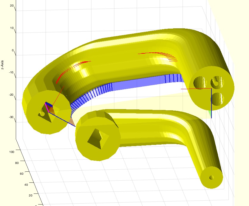 | % SGof2CPLTLcorrelate(CPLU,CPLO,TL) - creates a solid between two vessel structure CPL % (by Tim Lueth, VLFL-Lib, 2021-MÄR-25 as class: SURFACES) % % This is a progress of SGof2CPLzcorrelate, which is based on % SGof2CPLzbranch % If this fnctn used, you should consider, that the the minimal distance % from the origin of the individual frames define the required radius for % bending; the default is currectly recommended to 2.5 times the radius % of a tube. Make sure that you understand what happens if there are % several regions part of a contour. % NOTES: To avoid "DRAGON SKIN", the edges of the contour must be rounded % with CVLradial. % FUTURE: The next Improvement will be the separation of the regions and % to create individual pathes for each region, to avoid deformation of % currently forced shifst (Status of: 2021-03-29) % % Introduced first in SolidGeometry 5.1 % % See also: SGof2CPLzbranch, SGof2CPLzcorrelate, CVLof2CPLzcorrelate, % SGof2CPLzbranch % % [SGN,FLW,FLA,FLB,FLC,FLD]=SGof2CPLTLcorrelate([CPLU,CPLO,TL]) % === INPUT PARAMETERS === % CPLU: Contour A % CPLO: Contour B % TL: List of HT Matrices used follow the path % === OUTPUT RESULTS ====== % SGN: Solid Geometry % FLW: Facet of walls wrt to SGA.VL % FLA: Facet of floor wrt to SGA.VL % FLB: Facet of cover wrt to SGA.VL % FLC: Faces missing in A wrt to SGA.VL % FLD: Faces missing in B wrt to SGA.VL % % EXAMPLE: % TLofn([1 6]); T2=ans; % TLof2T(T2,'','',20); TL=ans % SGof2CPLTLcorrelate(CPLsample(26),CPLsample(27),TL); SGA=ans; % SGof2CPLTLcorrelate(CPLsample(26),CPLsample(27),TL); SGA=ans; % SGof2CPLTLcorrelate(CPLsample(7),CPLsample(8),TL); SGA=ans; % DRAGON SKIN CAUSE PROBLEMS % SGof2CPLTLcorrelate(CPLradialEdges(CPLsample(7),1),CPLradialEdges(CPLsample(8),1),TL); SGA=ans; % SGof2CPLTLcorrelate(CPLselectinout(CPLsample(38),[1 10]),CPLselectinout(CPLsample(39),[1 10]),TL); SGA=ans; % CVLof2CPLzcorrelate(CPLiold, CPLi) % CPLtransform(PLcircle(5),CPLi) % % See also: SGof2CPLzbranch, SGof2CPLzcorrelate, CVLof2CPLzcorrelate, % SGof2CPLzbranch % % % Copyright 2021 Tim C. Lueth |
exp_2021_03_22_linkrodcoll- creates a set of STL files to build robots with inline |
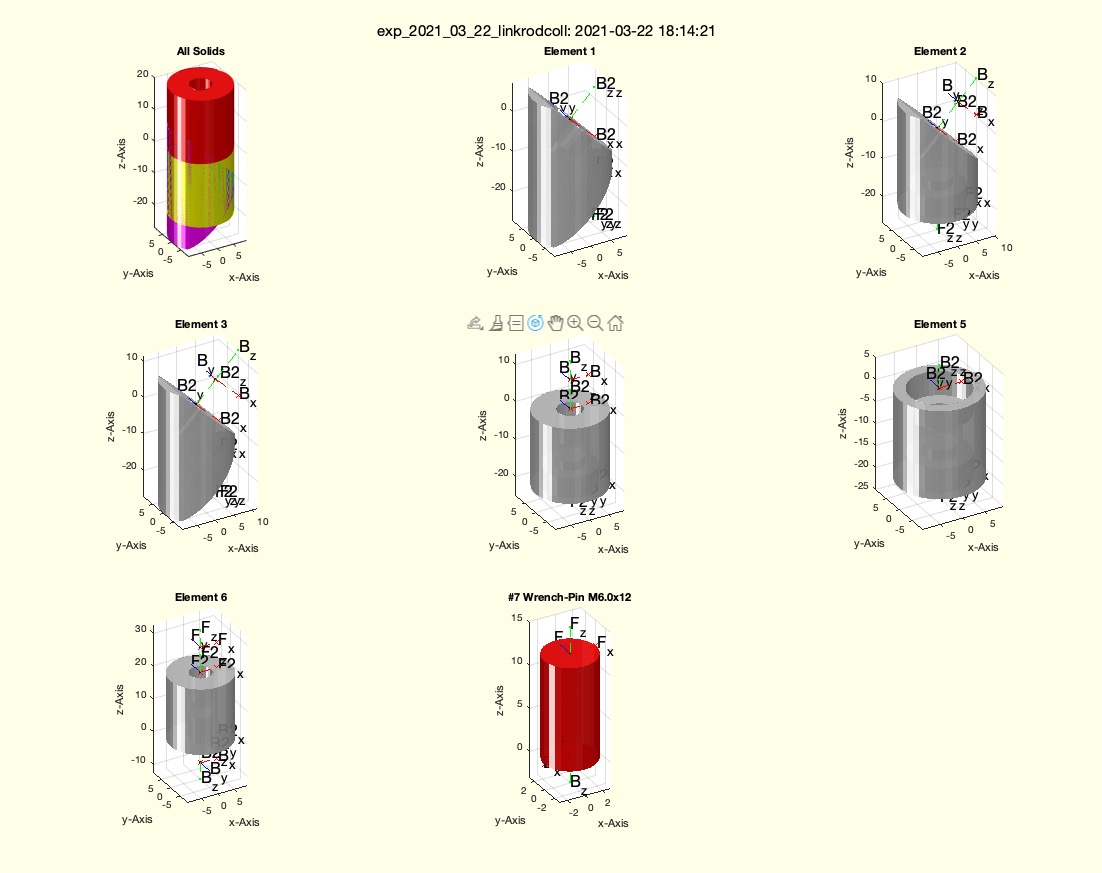 | % exp_2021_03_22_linkrodcoll - creates a set of STL files to build robots with inline % (by Tim Lueth, VLFL-Lib, 2021-MÄR-22 as class: EXPERIMENTS) % % Based on the fnctns SGsbpin and SGsblink (Status of: 2021-03-22) % % Introduced first in SolidGeometry 5.1 % % See also: SGsblink, SGsbpin % % exp_2021_03_22_linkrodcoll % % See also: SGsblink, SGsbpin % % % Copyright 2021 Tim C. Lueth |
SGsbpin(H,D,n,s)- returns a pin printined at 80% to be inserted by a hammer |
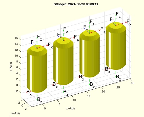 | % SGsbpin(H,D,n,s) - returns a pin printined at 80% to be inserted by a hammer % (by Tim Lueth, VLFL-Lib, 2021-MÄR-22 as class: PARAMETRIC DESIGN) % % Mechanisms Family using simple bearings (skate board size) (Status of: % 2021-03-23) % % Introduced first in SolidGeometry 5.1 % % See also: https://www.amazon.de/gp/product/B07NW97S64, SGiqpin, % SGsblink, SGsbbase % % SG=SGsbpin([H,D,n,s]) % === INPUT PARAMETERS === % H: Length/Height chamfer] of the Pin; default is [14 1] % D: Diameter of the Pin default is 6 % n: number of copies % s: fitting 'u' or 'b' (nominal value) % === OUTPUT RESULTS ====== % SG: Solid Geometry of a pin printined at 80% to be inserted by hammer % % EXAMPLE: % SGsbpin(14,'',4); SG=ans; % % See also: https://www.amazon.de/gp/product/B07NW97S64, SGiqpin, % SGsblink, SGsbbase % % % Copyright 2021 Tim C. Lueth |
looper(ind)- converts a sequence into a one-line sequence for a For loop |
 | % looper(ind) - converts a sequence into a one-line sequence for a For loop % (by Tim Lueth, VLFL-Lib, 2021-MÄR-21 as class: AUXILIARY PROCEDURES) % % At some point in Matlab, a line sequence seems to have been forced in % for loops. In any case, multiple sequences of the form (nx1) versus % (1xn) lead to annoying debugging. This fnctn always converts any % logical sequence or list of multiple lines to a single-line sequence % (Status of: 2021-03-21) % % Introduced first in SolidGeometry 5.1 % % See also: reshape, find % % ind=looper(ind) % === INPUT PARAMETERS === % ind: index list for a for-Loop % === OUTPUT RESULTS ====== % ind: corrent single line index list for a for-Loop % % EXAMPLE: % looper(true(3,3)) % looper(true(1,10)) % looper(true(10,1)) % looper([1 3 5 4]) % looper([1 3 5 4]') % % See also: reshape, find % % % Copyright 2021 Tim C. Lueth |
CVLofSGTFS(SG,T,sw,alp,thr)- returns from a (interactively selected) facet index the Contour and Transformation matric |
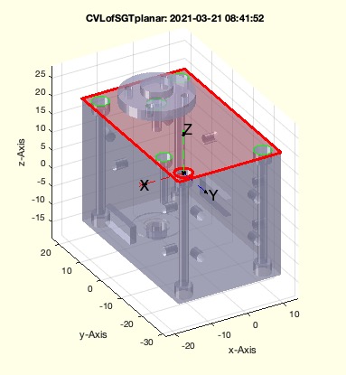 | % CVLofSGTFS(SG,T,sw,alp,thr) - returns from a (interactively selected) facet index the Contour and Transformation matric % (by Tim Lueth, VLFL-Lib, 2021-MÄR-21 as class: CLOSED POLYGON LISTS) % % CVLofSGT -requires SG.TFil of T (SG.TFil <== TR3mountingfaces, SGTui) % CVLofSGfi -requires only fi % CVLofSGTFS-requires only T - detects drilled surf not bore hole surf % % Currently, a renewed set of fnctns based on the relation of surfaces % and frames is emerging. Since part of the "language syntax" is hidden % in the fnctn names and the complexity of the geometric language is only % worked out over the years, and the syntax also changes slightly, it may % be that there are fnctns with similar names that do different things % and fnctns with different names that do similar things. This will have % to be corrected in later years, when an overall picture emerges. % (Status of: 2021-03-21) % % Introduced first in SolidGeometry 5.1 % % See also: SGTui, TR3mountingfaces, CVLofSGT, CVLofSGfi % % [CVL,fs,CPL,cp,ii]=CVLofSGTFS(SG,T,[sw,alp,thr]) % === INPUT PARAMETERS === % SG: Solid Geometry % T: optional facet index; default is '' => Interactive mode % sw: contour selection default is [0 10] % alp: alpha angle foe feature surface default is 0 % thr: threshold to detect in plan points; default is 1e-3 % === OUTPUT RESULTS ====== % CVL: Closed Contour in Space % fs: feature surface index fi that belongs to CVL % CPL: Planar Contour % cp: center points related to CPL % ii: facet index if selected interactively % % EXAMPLE: % CVLofSGTFS(YKLowerServo,'Hole02',[0 10]); % CVLofSGTFS(SGsample(25)); % % See also: SGTui, TR3mountingfaces, CVLofSGT, CVLofSGfi % % % Copyright 2021 Tim C. Lueth |
CVLofSGfi(SG,fi,sw)- returns from a (interactively selected) facet index the Contour and Transformation matric |
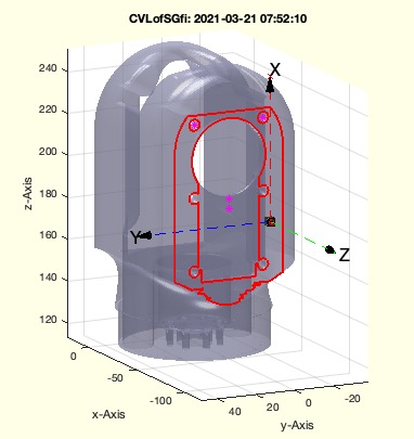 | % CVLofSGfi(SG,fi,sw) - returns from a (interactively selected) facet index the Contour and Transformation matric % (by Tim Lueth, VLFL-Lib, 2021-MÄR-20 as class: CLOSED POLYGON LISTS) % % This fnctn expects a facet index as input parameter and returs T at the % facet position. % CVLofSGT -requires SG.TFil of T (SG.TFil <== TR3mountingfaces, SGTui) % CVLofSGfi -requires only fi % CVLofSGTFS-requires only T - detects drilled surf not bore hole surf % % Currently, a renewed set of fnctns based on the relation of surfaces % and frames is emerging. Since part of the "language syntax" is hidden % in the fnctn names and the complexity of the geometric language is only % worked out over the years, and the syntax also changes slightly, it may % be that there are fnctns with similar names that do different things % and fnctns with different names that do similar things. This will have % to be corrected in later years, when an overall picture emerges. % (Status of: 2021-03-21) % % Introduced first in SolidGeometry 5.1 % % See also: CPLofVLFL, SGTui, TR3mountingfaces, CVLofSGT, CVLofSGTFS % % [CVL,T,CPL,cp,fi]=CVLofSGfi([SG,fi,sw]) % === INPUT PARAMETERS === % SG: Solid Geometry % fi: optional facet index; default is '' => Interactive mode % sw: contour selection default is [0 10] % === OUTPUT RESULTS ====== % CVL: Closed Contour in Space % T: Transformation Matrix (at position of fi) to create CVL from CPL (is % ona surface) % CPL: Planar Contour % cp: center points related to CPL % fi: facet index if selected interactively % % EXAMPLE: % CVLofSGfi(YKShoulder); % Select Manually % CVLofSGfi(YKShoulder,15432); % Select by fi % % See also: CPLofVLFL, SGTui, TR3mountingfaces, CVLofSGT, CVLofSGTFS % % % Copyright 2021-2022 Tim C. Lueth |
Tof2Tcrossez(T1,T2)- adjusts the position of frames relative to a crossing point with another frame |
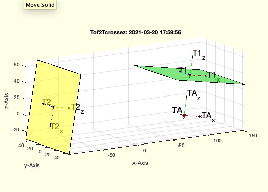 | % Tof2Tcrossez(T1,T2) - adjusts the position of frames relative to a crossing point with another frame % (by Tim Lueth, VLFL-Lib, 2021-MÄR-20 as class: KINEMATICS AND FRAMES) % % faster implementation than cross2L (Status of: 2021-03-20) % % Introduced first in SolidGeometry 5.1 % % See also: cross2L % % [TA,TB]=Tof2Tcrossez(T1,T2) % === INPUT PARAMETERS === % T1: Frame 1 % T2: Frame 2 % === OUTPUT RESULTS ====== % TA: Moved Frame 1 % TB: Moved Frame 1 % % EXAMPLE: % Tof2Tcrossez(SGTget(YKLower,'B'),SGTget(YKLower,'F')*TofR([0 pi 0])) % % See also: cross2L % % % Copyright 2021 Tim C. Lueth |
SGTframeselectrename(SG,Fset,Sel,new)- select frames, rename one, and remove the selected frames that were not renamed |
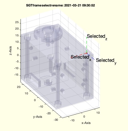 | % SGTframeselectrename(SG,Fset,Sel,new) - select frames, rename one, and remove the selected frames that were not renamed % (by Tim Lueth, VLFL-Lib, 2021-MÄR-20 as class: KINEMATICS AND FRAMES) % % This fnctn use usefull, if fnctns return several possible Frames of the % same type and there is a wish afterwards to select one of those and % remove the unused frames % Use it after SGTsetofRLcenter % (Status of: 2021-03-20) % % Introduced first in SolidGeometry 5.1 % % See also: SGTframeselect, SGTremove, SGTrename, SGTsetofRLcenter % % SG=SGTframeselectrename(SG,Fset,Sel,new) % === INPUT PARAMETERS === % SG: Solid Geometry % Fset: string selection has to start with % Sel: string selection has to end with % new: New Name for selection % === OUTPUT RESULTS ====== % SG: % % See also: SGTframeselect, SGTremove, SGTrename, SGTsetofRLcenter % % % Copyright 2021 Tim C. Lueth |
islink(fname)- returns wether a file is just a link |
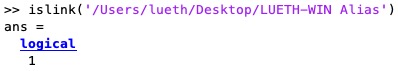 | % islink(fname) - returns wether a file is just a link % (by Tim Lueth, VLFL-Lib, 2021-MÄR-19 as class: FILE HANDLING) % % implemented at the moment only for mac osx 10.15.7. % This fnctn is important to avoid copying a link over the original % document when using copyfile or movefile and thus losing the content. % Links/aliases should not be copied (Status of: 2021-03-19) % % Introduced first in SolidGeometry 5.1 % % See also: isfolder, isdir, isfile % % islink=islink(fname) % === INPUT PARAMETERS === % fname: file name % === OUTPUT RESULTS ====== % islink: yes if the fname is a link % % EXAMPLE: % islink('/Users/lueth/Desktop/LUETH-WIN Alias') % % See also: isfolder, isdir, isfile % % % Copyright 2021 Tim C. Lueth |
VLofT(TL)- returns the origin T(1:3,4) of a frame list |
 | % VLofT(TL) - returns the origin T(1:3,4) of a frame list % (by Tim Lueth, VLFL-Lib, 2021-MÄR-18 as class: KINEMATICS AND FRAMES) % % Introduced first in SolidGeometry 5.1 % % See also: VLofSG % % VL=VLofT(TL) % === INPUT PARAMETERS === % TL: [n*4 x 4] list or cell list of 4x4 frames % === OUTPUT RESULTS ====== % VL: vertex list of the frame origins % % See also: VLofSG % % % Copyright 2021 Tim C. Lueth |
SGTremoverelT(SG,T,rel)- removes frames from an SGT that fullfill a condition |
 | % SGTremoverelT(SG,T,rel) - removes frames from an SGT that fullfill a condition % (by Tim Lueth, VLFL-Lib, 2021-MÄR-18 as class: KINEMATICS AND FRAMES) % % relations are % (u)nder % (a)above % (o)n plane (Status of: 2021-03-18) % % Introduced first in SolidGeometry 5.1 % % See also: SGTremove, VLisbelowT % % SG=SGTremoverelT(SG,T,[rel]) % === INPUT PARAMETERS === % SG: Solid Geometry with Frames % T: Cutting Frame % rel: relation such as 'uo' ==means under and on plane % === OUTPUT RESULTS ====== % SG: SOlid Geometry with Frames only that fulfill the condition rel % % EXAMPLE: % load YKLower.mat; SG=YKLower % SGTremoverelT(SG,TofPez('',[1 0 0]),'u') % under % SGTremoverelT(SG,TofPez('',[1 0 0]),'a') % above % % % See also: SGTremove, VLisbelowT % % % Copyright 2021 Tim C. Lueth |
VLisbelowT(VL,T,thr)- returns wether a list of points or a cell list of frames is under a frame |
 | % VLisbelowT(VL,T,thr) - returns wether a list of points or a cell list of frames is under a frame % (by Tim Lueth, VLFL-Lib, 2021-MÄR-18 as class: KINEMATICS AND FRAMES) % % Introduced first in SolidGeometry 5.1 % % See also: distE, distT, planedistanceofT % % [b,a,o]=VLisbelowT(VL,[T,thr]) % === INPUT PARAMETERS === % VL: Vertex List % T: Frame the describe plae % thr: threshold for on; default is 1e-5 % === OUTPUT RESULTS ====== % b: logical of below % a: logical of above % o: logical of on % % EXAMPLE: % VL=rand(10,3); VLisbelowT(VL,TofPez([0 0 1],[0 1 1 ])) % % See also: distE, distT, planedistanceofT % % % Copyright 2021 Tim C. Lueth |
CVLsortlinestraight(XVL)- returns a reordered CVL |
 | % CVLsortlinestraight(XVL) - returns a reordered CVL % (by Tim Lueth, VLFL-Lib, 2021-MÄR-17 as class: CLOSED POLYGON LISTS) % % If curves or lines are generated automatically from precondition, There % are some situations where preconditions in combination with numerical % inaccuracies lead to strong kinks and consequently to wrong % calculations of normal vectors. (Status of: 2021-03-17) % % Introduced first in SolidGeometry 5.1 % % See also: TLofCVL, CVLsortlinedistance % % NVL=CVLsortlinestraight(XVL) % === INPUT PARAMETERS === % XVL: Original Line in 3D Space % === OUTPUT RESULTS ====== % NVL: Corrected Line in 3D Space % % EXAMPLE: % CVLsortlinestraight([0 0; 6 0; 5 0; 4 0; 7 0; 6.5 0; 10 0]) % % See also: TLofCVL, CVLsortlinedistance % % % Copyright 2021 Tim C. Lueth |
diffTincz(TA,TB)- returns for Frames the relative incliniation of the ez vector of B wrt to A |
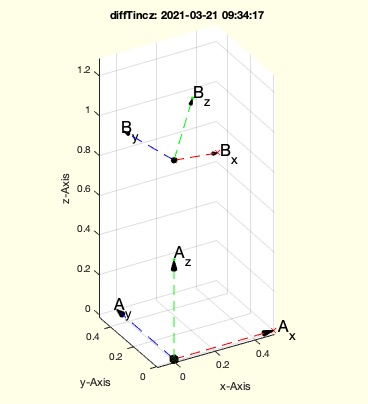 | % diffTincz(TA,TB) - returns for Frames the relative incliniation of the ez vector of B wrt to A % (by Tim Lueth, VLFL-Lib, 2021-MÄR-17 as class: ANALYTICAL GEOMETRY) % % makes no sense for orthogonal vectors. ez should show into the same % direction % use atan2 of the x axis % seee also diffanglew afterwards for relative angles % This fucntion is used in TLadjustR (Status of: 2021-03-21) % % Introduced first in SolidGeometry 5.1 % % See also: diffT, TLadjustR, diffanglew, diffTrotz % % w=diffTincz(TA,TB) % === INPUT PARAMETERS === % TA: Frame A % TB: Frame b % === OUTPUT RESULTS ====== % w: relative rotation of Bx relative to Ax % % EXAMPLE: % diffTincz(eye(4),TofR(rot(0,pi/10,pi/10),[0 0 1])) % % See also: diffT, TLadjustR, diffanglew, diffTrotz % % % Copyright 2021 Tim C. Lueth |
TofFSRLcenter(SG,fi,al,minmaxR,minmaxW)- returns a Frame based on the smallest found radii inside a surface |
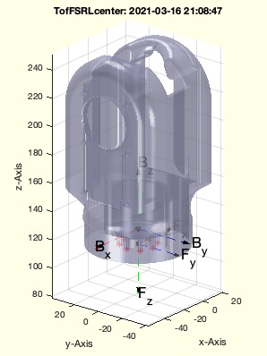 | % TofFSRLcenter(SG,fi,al,minmaxR,minmaxW) - returns a Frame based on the smallest found radii inside a surface % (by Tim Lueth, VLFL-Lib, 2021-MÄR-16 as class: KINEMATICS AND FRAMES) % % Mainly used as interactive fnctn, it can be also used based on a single % face index (Status of: 2021-03-16) % % Introduced first in SolidGeometry 5.1 % % See also: SGTsetofRLcenter % % [TF,TB,RL,URL]=TofFSRLcenter([SG,fi,al,minmaxR,minmaxW]) % === INPUT PARAMETERS === % SG: Solid Geometry % fi: optional fi; if empty, interactive mode % al: alpha value for surface detection; default is 0 % minmaxR: default is [1.1 4] % minmaxW: default is [170 360] % === OUTPUT RESULTS ====== % TF: Front Frame % TB: Backside Frame % RL: Radii list % URL: selected radii % % EXAMPLE: % load Yannick_robot.mat % or loadweb % SG=YKLower; % TofFSRLcenter(SG) % % See also: SGTsetofRLcenter % % % Copyright 2021 Tim C. Lueth |
SGTsetofRLcenter(SG,fi,N,minmaxR,minmaxW)- returns a frame of a surface that is defined by drilling holes |
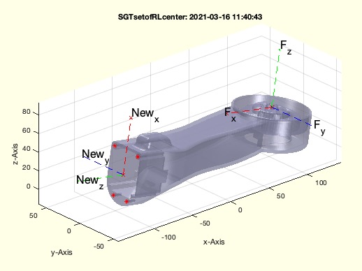 | % SGTsetofRLcenter(SG,fi,N,minmaxR,minmaxW) - returns a frame of a surface that is defined by drilling holes % (by Tim Lueth, VLFL-Lib, 2021-MÄR-16 as class: KINEMATICS AND FRAMES) % % Introduced first in SolidGeometry 5.1 % % See also: TofFSRLcenter % % SG=SGTsetofRLcenter([SG,fi,N,minmaxR,minmaxW]) % === INPUT PARAMETERS === % SG: Solid Geometry % fi: optiona facet index; default is ''; ==> interavtive % N: Name of Frame % minmaxR: minmax for radius default is [1.1 1.9] % minmaxW: minmax for arc circle default is [170 360] % === OUTPUT RESULTS ====== % SG: Solid including Frame % % EXAMPLE: % load Yannick_robot.mat % SGTsetofRLcenter(YKLower); SG=ans; % % See also: TofFSRLcenter % % % Copyright 2021 Tim C. Lueth |
diffanglew(w1,w2)- returns the shortest distance from angle 1 to angle 2 |
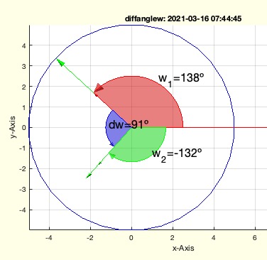 | % diffanglew(w1,w2) - returns the shortest distance from angle 1 to angle 2 % (by Tim Lueth, VLFL-Lib, 2021-MÄR-15 as class: ANALYTICAL GEOMETRY) % % also imp (Status of: 2021-03-16) % % Introduced first in SolidGeometry 5.1 % % See also: diffT, TLadjustR, diffTrotz, diffTincz % % dw=diffanglew(w1,w2) % === INPUT PARAMETERS === % w1: angle w1 % w2: angle w2 % === OUTPUT RESULTS ====== % dw: shortes turning angle from w1 to w2 % % EXAMPLE: % diffanglew(-2.4,+2.3); % diffanglew(+2.4,-2.3); % diffanglew(+12.4,-2.3); % % % See also: diffT, TLadjustR, diffTrotz, diffTincz % % % Copyright 2021 Tim C. Lueth |
diffTrotz(TA,TB)- returns for Frames the relative rotation of the ez vector of B wrt to A |
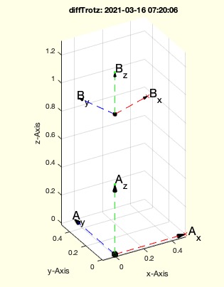 | % diffTrotz(TA,TB) - returns for Frames the relative rotation of the ez vector of B wrt to A % (by Tim Lueth, VLFL-Lib, 2021-MÄR-15 as class: ANALYTICAL GEOMETRY) % % makes no sense for orthogonal vectors. ez should show into the same % direction % use atan2 of the x axis % seee also diffanglew afterwards for relative angles % This fucntion is used in TLadjustR (Status of: 2021-03-16) % % Introduced first in SolidGeometry 5.1 % % See also: diffT, TLadjustR, diffanglew, diffTincz % % w=diffTrotz(TA,TB) % === INPUT PARAMETERS === % TA: Frame A % TB: Frame b % === OUTPUT RESULTS ====== % w: relative rotation of Bx relative to Ax % % EXAMPLE: % diffTrotz(eye(4),TofR(rot(0,0,pi/10),[0 0 1])) % % See also: diffT, TLadjustR, diffanglew, diffTincz % % % Copyright 2021 Tim C. Lueth |
SGwriteSTLshrinked(SG,fname,size)- writes shrinked STL files on disk |
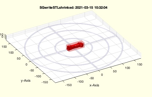 | % SGwriteSTLshrinked(SG,fname,size) - writes shrinked STL files on disk % (by Tim Lueth, VLFL-Lib, 2021-MÄR-14 as class: 3D MANUFACTURING) % % This fnctn stores the factor as a persistent variable. If the size % factor is not explicitly overwritten, the factor from the last call is % used. In the future, the fnctn will also analyze SG-cells, determine % the largest factor and shrink all parts with this factor. (Status of: % 2021-03-15) % % Introduced first in SolidGeometry 5.1 % % See also: SGshrinktofit, SGwriteSTL % % sname=SGwriteSTLshrinked(SG,[fname,size]) % === INPUT PARAMETERS === % SG: Solid Gemetry % fname: optional file name % size: maximum dimensions in mm oder shinking factor; default is 100mm % === OUTPUT RESULTS ====== % sname: file name % % EXAMPLE: % loadweb Yannick_robot.mat % SGwriteSTLshrinked(YKUpper,'',100); % SGwriteSTLshrinked(YKLower); % SGwriteSTLshrinked(YKBase); % SGwriteSTLshrinked(YKShoulder); % % % See also: SGshrinktofit, SGwriteSTL % % % Copyright 2021 Tim C. Lueth |
SGcutTextrudeT(SG,T,Td,olap,type,unite)- returns a cutted an elongated solid by extrusion of the crosssection plane |
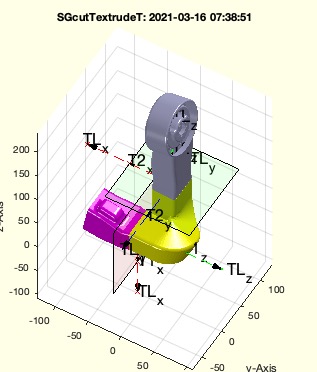 | % SGcutTextrudeT(SG,T,Td,olap,type,unite) - returns a cutted an elongated solid by extrusion of the crosssection plane % (by Tim Lueth, VLFL-Lib, 2021-MÄR-14 as class: KINEMATICS AND FRAMES) % % Cutting, extending, shortening, bending of existing robotic joints % using Yannich's untearm as an example. (Status of: 2021-03-29) % % Introduced first in SolidGeometry 5.1 % % See also: SGcutT, CVLofopenfaces, TofPez, VLFL_EXP65, SGTcutTextrude, % SGcut2TextrudeT % % [SGN,T,TN]=SGcutTextrudeT([SG,T,Td,olap,type,unite]) % === INPUT PARAMETERS === % SG: Solid Geometry % T: Cutting Frame % Td: Straight distance in z or Relative link % olap: overlap of new and old parts % type: straight, rad, rmax,tan; default is straight % unite: if true and possible; fnctn tries to combine the three elements % again to one % === OUTPUT RESULTS ====== % SGN: Result if there is only one solid; unite=true % T: Transformation matrix of click, Global Start Frame % TN: Global End Frame % % EXAMPLE: load Yannick_robot.mat % Or Use loadweb % % SGcutTextrudeT(YKLower,T, TofPez([50 +90 100],[0 0 -1],pi/3),'','rad'); SGN=ans; view(10,30); % SGcutTextrudeT(YKLower,T, TofPez([50 +90 100],[0 0 -1],pi/3),'','tan'); SGN=ans; view(10,30); % SGcutTextrudeT(YKLower,T, TofPez([50 +90 100],[0 0 +1],pi/3),'','rad'); SGN=ans; view(10,30); % SGcutTextrudeT(YKLower,T, TofPez([50 +90 100],[0 0 +1],pi/3),'','tan'); SGN=ans; view(10,30); % % See also: SGcutT, CVLofopenfaces, TofPez, VLFL_EXP65, SGTcutTextrude, % SGcut2TextrudeT % % % Copyright 2021 Tim C. Lueth |
TLadjustR(TL,R1,R2)- takes a List of Frames and adjustst start and end frame to T1 and T2 |
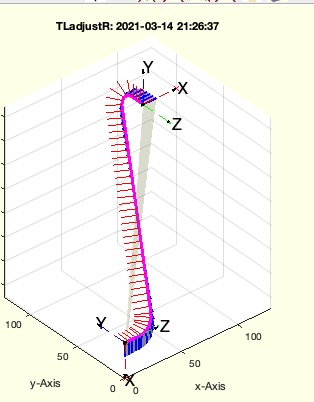 | % TLadjustR(TL,R1,R2) - takes a List of Frames and adjustst start and end frame to T1 and T2 % (by Tim Lueth, VLFL-Lib, 2021-MÄR-14 as class: KINEMATICS AND FRAMES) % % The ez vector has to show into the right direction. % This fnctn uses diffanglew, and diffTrotz to adjust the start frame of % a list to a default and rotate all frames minimally to reach the end % frame. Used after TLofCVL, or VLradialEdges2T, or CVLof2T, to build a % path between two frames, and VLedgeNormal to determine the % contour-following normal vectors. From normal and orthogonal vectors % the frame sequence or frame list is generated. The frame list is then % adapted to the start orientation and end orientation by twisting. % (Status of: 2021-03-15) % % Introduced first in SolidGeometry 5.1 % % See also: diffanglew, diffTrotz % TLofCVL, CVLof2T % % TL=TLadjustR(TL,[R1,R2]) % === INPUT PARAMETERS === % TL: Frame list % R1: R or T Matrix % R2: R or T Matrix % === OUTPUT RESULTS ====== % TL: Corrected Frame list % % EXAMPLE: % T1=TofPez([0 0 0],[1 0 0]);T2=TofPez([100 100 100],[0 -1 0]); SGfigure(-30,30); tplot(T1,40); tplot(T2,40); % CVLof2T(T1,T2,'',10,'rad'); CVL=ans; % TLofCVL(CVL,10,T1,T2,'rad',false,5); TL=ans % TLadjustR(TL,T1,T2) % % See also: diffanglew, diffTrotz % TLofCVL, CVLof2T % % % Copyright 2021 Tim C. Lueth |
TLplots(TL,);- plots a list of HT matrices with plane, normal vector and prthogonal vectors |
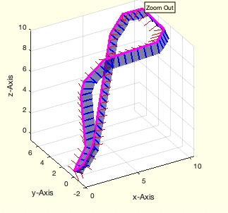 | % TLplots(TL,); - plots a list of HT matrices with plane, normal vector and prthogonal vectors % (by Tim Lueth, VLFL-Lib, 2021-MÄR-14 as class: KINEMATICS AND FRAMES) % % completely different to tlplot (Status of: 2021-03-14) % % Introduced first in SolidGeometry 5.1 % % See also: tplot, VLNLOLplot % % h=TLplots(TL,[]); % === INPUT PARAMETERS === % TL: Lust of HT matrices % === OUTPUT RESULTS ====== % h: handle to graphics % % EXAMPLE: % SGfigure(-30,30); TLplots(TLofCVL(VLsample(8),03)); % % See also: tplot, VLNLOLplot % % % Copyright 2021 Tim C. Lueth |
VLNLOLplot(VL,NL,OL)- plot an open or closed CVL including Edge Normal Vector and Edge Orthogonal Vector |
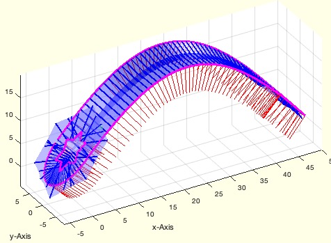 | % VLNLOLplot(VL,NL,OL) - plot an open or closed CVL including Edge Normal Vector and Edge Orthogonal Vector % (by Tim Lueth, VLFL-Lib, 2021-MÄR-14 as class: CLOSED POLYGON LISTS) % % Auxiliary fnctn for plotting pathes in 3D Space. Similar to the output % of VLedgeNormal % (Status of: 2021-03-14) % % Introduced first in SolidGeometry 5.1 % % See also: VLedgeNormal, VLNLplot, VLELplot, VLFLplot % % h=VLNLOLplot(VL,[NL,OL]) % === INPUT PARAMETERS === % VL: MAGENTA Path, required % NL: RED EDGE Normal Vectors % OL: Blue = Edge Orthogonal Vector; RED=last, Green= first % === OUTPUT RESULTS ====== % h: handle to graphic % % EXAMPLE: % SGfigure(-30,30); VLNLOLplot(VLsample(15)); % % SGfigure(-30,30); VLNLOLplot(VLsample(32)); % % See also: VLedgeNormal, VLNLplot, VLELplot, VLFLplot % % % Copyright 2021 Tim C. Lueth |
exp_2021_03_14_yannickcut3(SG,T,Td,unite,type)- EXPERIMENT to modify the links of the Yannick robot |
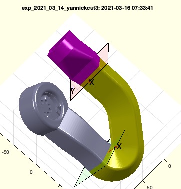 | % exp_2021_03_14_yannickcut3(SG,T,Td,unite,type) - EXPERIMENT to modify the links of the Yannick robot % (by Tim Lueth, VLFL-Lib, 2021-MÄR-14 as class: EXPERIMENTS) % % Cutting, extending, shortening, bending of existing robotic joints % using Yannich's untearm as an example. % ==> FInalizes and corrented as SGcutTextrudeT (Status of: 2021-03-16) % % Introduced first in SolidGeometry 5.1 % % See also: SGcutT, CVLofopenfaces % % [SGN,T]=exp_2021_03_14_yannickcut3([SG,T,Td,unite,type]) % === INPUT PARAMETERS === % SG: Solid Geometry % T: Cutting Frame % Td: Straight distance in z or Relative link % unite: if true; fnctn stries to combine the three elements again to one % type: % === OUTPUT RESULTS ====== % SGN: Result if there is only one solid; unite=true % T: Transformation matrix of click % % EXAMPLE: loadweb Yannick_robot.mat % % exp_2021_03_13_yannickcut2(YKLower,T, TofR(rot(pi/6,pi/6,pi/6),[0 0 300]),false); SGN=ans; % % See also: SGcutT, CVLofopenfaces % % % Copyright 2021 Tim C. Lueth |
exp_2021_03_13_yannickcut2(SG,T,Td,unite)- EXPERIMENT to modify the links of the Yannick robot |
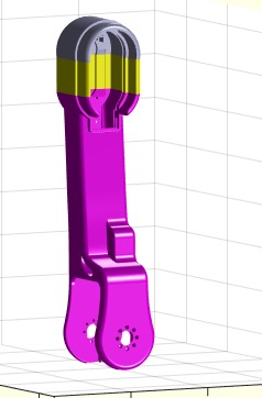 | % exp_2021_03_13_yannickcut2(SG,T,Td,unite) - EXPERIMENT to modify the links of the Yannick robot % (by Tim Lueth, VLFL-Lib, 2021-MÄR-13 as class: EXPERIMENTS) % % Cutting, extending, shortening, bending of existing robotic joints % using Yannich's untearm as an example. (Status of: 2021-03-13) % % Introduced first in SolidGeometry 5.1 % % See also: SGcutT, CVLofopenfaces % % [SGN,T]=exp_2021_03_13_yannickcut2([SG,T,Td,unite]) % === INPUT PARAMETERS === % SG: Solid Geometry % T: Cutting Frame % Td: Straight distance in z or Relative link % unite: if true; fnctn stries to combine the three elements again to one % === OUTPUT RESULTS ====== % SGN: Result if there is only one solid; unite=true % T: Transformation matrix of click % % EXAMPLE: % loadweb Yannick_robot.mat % exp_2021_03_13_yannickcut2(YKLower,T, TofR(rot(pi/6,pi/6,pi/6),[0 0 300]),false); SGN=ans; % % See also: SGcutT, CVLofopenfaces % % % Copyright 2021 Tim C. Lueth |
exp_2021_03_12_yannickcut(SG,d,unite)- EXPERIMENT to modify the links of the Yannick robot |
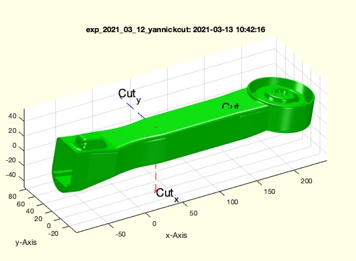 | % exp_2021_03_12_yannickcut(SG,d,unite) - EXPERIMENT to modify the links of the Yannick robot % (by Tim Lueth, VLFL-Lib, 2021-MÄR-12 as class: EXPERIMENTS) % % Cutting, extending, shortening, bending of existing robotic joints % using Yannich's untearm as an example. (Status of: 2021-03-13) % % Introduced first in SolidGeometry 5.1 % % SGN=exp_2021_03_12_yannickcut([SG,d,unite]) % === INPUT PARAMETERS === % SG: Solid Geometry % d: Straight distance in z % unite: if true; fnctn stries to combine the three elements again to one % === OUTPUT RESULTS ====== % SGN: Result if there is only one solid; unite=true % % EXAMPLE: % loadweb Yannick_robot.mat % exp_2021_03_12_yannickcut(YKLower, 100,true) % % % Copyright 2021 Tim C. Lueth |
SGrodlink(L,RF,RB,ezF,ezB,llf,w)- returns a cylinder with inclined top and bottom surfaces |
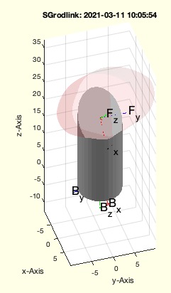 | % SGrodlink(L,RF,RB,ezF,ezB,llf,w) - returns a cylinder with inclined top and bottom surfaces % (by Tim Lueth, VLFL-Lib, 2021-MÄR-11 as class: PARAMETRIC DESIGN) % % This fnctn is used to design wrists for kinematic chains. % Bccause of the still problematic boolean fnctn it fails from time to % time for w>0 && w<2*pi) due to the significantly more complex % calculation of in-plane rotated contours (Status of: 2021-03-11) % % Introduced first in SolidGeometry 5.1 % % See also: SGspherelink, SGcylinder % % SG=SGrodlink([L,RF,RB,ezF,ezB,llf,w]) % === INPUT PARAMETERS === % L: Length of the rod, distance of the frames % RF: [Rx Ry] at the upper end of the rod % RB: [Rx Ry] at the lower end of the rod % ezF: ez at the upper end of the rod % ezB: ez at the lower end of the rod % llf: Length of follower link as factor of max (RF) % w: rotation angle default is 0 % === OUTPUT RESULTS ====== % SG: Final solid Geometry % % EXAMPLE: % SGrodlink(20,5,5) % SGrodlink(20,5,5,[1 0 1]) % SGrodlink(20,5,5,[1 0 0],'',2,pi/2*1.5) % % See also: SGspherelink, SGcylinder % % % Copyright 2021 Tim C. Lueth |
exp_2021_03_10_rodlinkjaco(L,sdl,hex,fit,rod,LL)- |
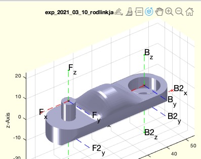 | % exp_2021_03_10_rodlinkjaco(L,sdl,hex,fit,rod,LL) - % (by Tim Lueth, VLFL-Lib, 2021-MÄR-10 as class: EXPERIMENTS) % % Introduced first in SolidGeometry 5.1 % % exp_2021_03_10_rodlinkjaco([L,sdl,hex,fit,rod,LL]) % === INPUT PARAMETERS === % L: % sdl: % hex: % fit: % rod: % LL: % % % Copyright 2021 Tim C. Lueth |
crosspointVLFLfi(VL,FL,fi);- returns the self crosspoints of a surface normal vector |
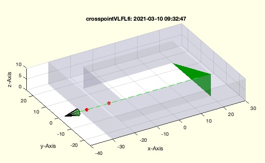 | % crosspointVLFLfi(VL,FL,fi); - returns the self crosspoints of a surface normal vector % (by Tim Lueth, VLFL-Lib, 2021-MÄR-10 as class: SURFACES) % % This fnctn is used to check for outside (Status of: 2021-03-10) % % Introduced first in SolidGeometry 5.1 % % See also: crosspointVLFL, SGcheckfacedist, SGinsideSurface % % [cp,t,fic,fid]=crosspointVLFLfi(VL,FL,fi); % === INPUT PARAMETERS === % VL: Vertrex list or SG % FL: Facet List % fi: facet index % === OUTPUT RESULTS ====== % cp: cross point on surface, empty if there is no crossing point % t: distance (t * ez) % fic: facet index of 1st crossed surface % fid: full list of facet index and distance [fi, d] % % EXAMPLE: % crosspointVLFLfi(SGsample(29),'',20) % two cross points % crosspointVLFLfi(SGsample(29),'',32) % no cross point % % See also: crosspointVLFL, SGcheckfacedist, SGinsideSurface % % % Copyright 2021 Tim C. Lueth |
SGsbbase(L,sdl,hex,fit)- Creates a base for a simple ball bearing four-bar linkage |
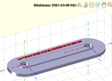 | % SGsbbase(L,sdl,hex,fit) - Creates a base for a simple ball bearing four-bar linkage % (by Tim Lueth, VLFL-Lib, 2021-MÄR-08 as class: PARAMETRIC DESIGN) % % writes a STL file if called without argout. The dimension labeling % takes place only if there is no output argument (Status of: 2021-03-09) % % Introduced first in SolidGeometry 5.1 % % See also: https://www.amazon.de/gp/product/B07NW97S64, % SGManipulatorLink, SGsblink % % B=SGsbbase([L,sdl,hex,fit]) % === INPUT PARAMETERS === % L: Distance between A0 and B0; default is [50 0 0] % sdl: [Di Do th w] Inner and Outer Diameter, width, and wall thickness % hex: optional diameter of an inner hexagon in the shaft % fit: if true, the pin use slfit('b') and will interfere; default is % false % === OUTPUT RESULTS ====== % B: Simple Bearing Base for a linkage with NO TEXT % % EXAMPLE: SGfigure; fourBarLinkageplotanim([110,80,100,50]) % Franz Irlinger's 4 Bar Linkage % SGsbbase(110) % 110mm with two bearings % SGsbbase([110 1 1]) % 110mm with two pins % % % See also: https://www.amazon.de/gp/product/B07NW97S64, % SGManipulatorLink, SGsblink % % % Copyright 2021 Tim C. Lueth |
SGsblink(L,sdl,hex,fit,rod)- returns a link for insertion of a bearing, optional a sleeve, and an inner hexagon at the shaft end |
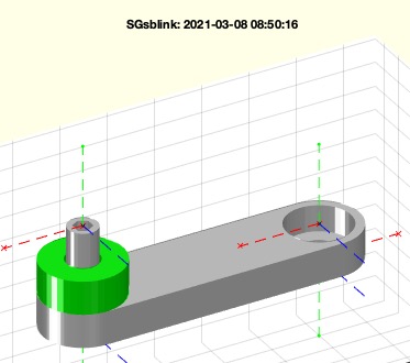 | % SGsblink(L,sdl,hex,fit,rod) - returns a link for insertion of a bearing, optional a sleeve, and an inner hexagon at the shaft end % (by Tim Lueth, VLFL-Lib, 2021-MÄR-07 as class: PARAMETRIC DESIGN) % % If slfit('b') is used for the pin, i.e. the pin has the exact shape, % the pin has an interfence fit inside the bearing. It can be inserted by % a hammer but the pin and the part will be destoyed (even with % wallthickness of 1.2mm) at removal from the bearing. % The fnctn can also create rods als link (Status of: 2021-03-10) % % Introduced first in SolidGeometry 5.1 % % See also: https://www.amazon.de/gp/product/B07NW97S64, % SGManipulatorLink, SGiqlink, SGsbbase, SGrodlink % % [A,SL_F]=SGsblink([L,sdl,hex,fit,rod]) % === INPUT PARAMETERS === % L: [L level-F Level-B]; Distance and level [-n .. 0 .. n]; default is % [50 1 0] % sdl: [Di Do b] Inner D, Outer D and width of Bearing; default [6 13 5] % hex: optional diameter of an inner hexagon in the shaft % fit: if true, the pin use slfit('b') and will interfere; default is % false % rod: a rod is created instead of a link; use true or ez vectors % === OUTPUT RESULTS ====== % A: Geometry of the Link % SL_F: SLEEVE if abs(level)>1 for Pin 1 % % EXAMPLE: SGfigure; fourBarLinkageplotanim([110,70,90,50]); % SGsblink([50 -2],[6 13 5],3) % SGsblink([50 -2],[6 13 5],3,true) % SGsblink([50 1 -1]); % SGsblink([50 0 0]); % SGsblink([50 1],[6 13 5],3,'',true) % creates a rod % SGsblink([20 0 0],[6 13 5 2.5],'','',[1 0 1]); B=ans % SGsblink([10 1 0],[6 13 5 2.7],'','',true); B=ans % SGsblink([20 0 0],[6 13 5 2.7],'','',[1 0 1; -1 0 1]); B=ans % % % See also: https://www.amazon.de/gp/product/B07NW97S64, % SGManipulatorLink, SGiqlink, SGsbbase, SGrodlink % % % Copyright 2021 Tim C. Lueth |
ejectvolume(vnames)- Auxiliary fnct to unmount and eject a extrenal drive such as a sd card |
 | % ejectvolume(vnames) - Auxiliary fnct to unmount and eject a extrenal drive such as a sd card % (by Tim Lueth, VLFL-Lib, 2021-MÄR-07 as class: FILE HANDLING) % % currently only available on mac (Status of: 2021-03-07) % % Introduced first in SolidGeometry 5.1 % % See also: existvolume, gcode2sdcard % % ejectvolume([vnames]) % === INPUT PARAMETERS === % vnames: name of voume or directory of volume % % EXAMPLE: % ejectvolume('/Volumes/AP5TIMLUETH') % % See also: existvolume, gcode2sdcard % % % Copyright 2021 Tim C. Lueth |
islfit(dm,de,diam,AP)- returns a probable fitting for an expected 3D Printer from two dimenions |
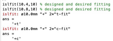 | % islfit(dm,de,diam,AP) - returns a probable fitting for an expected 3D Printer from two dimenions % (by Tim Lueth, VLFL-Lib, 2021-MÄR-06 as class: PARAMETRIC DESIGN) % % inverse fnctn to slfit. Useful if STL files were created by scientist % or hobbies, who used their knowledge on the inaccuries, oversize, % undersize of the 3D-printout with respect to an STL file and designed % their own fitting dimension. These STLs can then only be sliced for the % respective printer under consideration, because on other 3D printers % they lead to mismatched connections or loose ball bearing seats or % generally to incorrect fits. (Status of: 2021-03-07) % % Introduced first in SolidGeometry 5.1 % % See also: slfit, DIN4AMfitting % % [ss,AP,s]=islfit(dm,de,[diam,AP]) % === INPUT PARAMETERS === % dm: Measured Dimension DIAMETER of a bore % de: Expected Dimension DIAMETER of a bore % diam: optional specific printer name if not default one % AP: Name of Printer for fitting test % === OUTPUT RESULTS ====== % ss: single char abbreviation % AP: full name of printer % s: full fitting description % % EXAMPLE: % islfit(10.4,10) % designed and desired fitting if the bore should be 10.0 but the STL shows 10.4 % islfit(10.8,10) % designed and desired fitting if the bore should be 10.0 but the STL shows 10.4 % % See also: slfit, DIN4AMfitting % % % Copyright 2021-2022 Tim C. Lueth |
exp_2021_03_06_Bearing- Experiment to create simple but practicable bearing solutions for rotating joints |
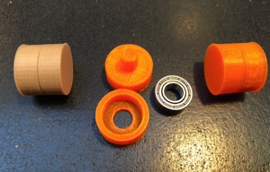 | % exp_2021_03_06_Bearing - Experiment to create simple but practicable bearing solutions for rotating joints % (by Tim Lueth, VLFL-Lib, 2021-MÄR-06 as class: EXPERIMENTS) % % This is a simple - but successful experiment - using SG-Lib's fit % generation fnctns to quickly and specifically construct revolute joint % solutions. Programming the example takes 30 minutes, printing 15 % minutes. The joint was immediately usable. (Status of: 2021-03-06) % % Introduced first in SolidGeometry 5.1 % % See also: https://www.amazon.de/gp/product/B07NW97S64 % % X=exp_2021_03_06_Bearing % === OUTPUT RESULTS ====== % X: Two solids, arranged for printing % % EXAMPLE: % exp_2021_03_06_Bearing % % See also: https://www.amazon.de/gp/product/B07NW97S64 % % % Copyright 2021 Tim C. Lueth |
gcodecopytemp (fname,)- just makes copies of an ANYCUBIC/CURA gcode file with changed hot end and base temperature |
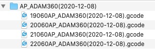 | % gcodecopytemp (fname,) - just makes copies of an ANYCUBIC/CURA gcode file with changed hot end and base temperature % (by Tim Lueth, VLFL-Lib, 2021-MÄR-03 as class: 3D MANUFACTURING) % % Introduced first in SolidGeometry 5.1 % % See also: SGgcodefilechangetemp, filenameadddate4gcode, gcodecleanup % % gcodecopytemp(fname,[]) % === INPUT PARAMETERS === % fname: existing gcode file name % % EXAMPLE: % gcodecopytemp('/Volumes/AP5TIMLUETH/AP_ADAM360(2020-12-08)/22060AP_ADAM360(2020-12-08).gcode') % % See also: SGgcodefilechangetemp, filenameadddate4gcode, gcodecleanup % % % Copyright 2021 Tim C. Lueth |
CPLconvexhulloutline(CPL,b,r,t)- creates a ONE region CPL from several regions of a CPL by using the convex hull |
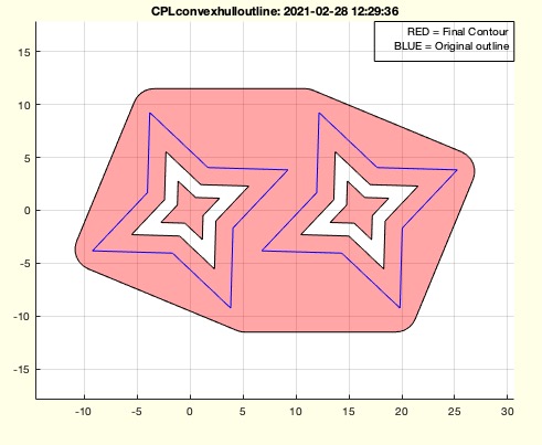 | % CPLconvexhulloutline(CPL,b,r,t) - creates a ONE region CPL from several regions of a CPL by using the convex hull % (by Tim Lueth, VLFL-Lib, 2021-FEB-28 as class: CLOSED POLYGON LISTS) % % By using the parameter t, a lot of different possibilities exist: % CPLconvexhulloutline(CPLsample(14),1,0,'default'); % convexhull % CPLconvexhulloutline(CPLsample(14),1,0,'delaunay');% convexhulldelaunay % CPLconvexhulloutline(CPLsample(14),1,0,'fillgap'); % convexhullfillgap % (Status of: 2021-02-28) % % Introduced first in SolidGeometry 5.1 % % See also: CPLconvexhull, CPLconvexhulldelaunay, CPLconvexhullfillgap, % CPLselectinout, CPLradialEdges % % CPLN=CPLconvexhulloutline(CPL,[b,r,t]) % === INPUT PARAMETERS === % CPL: Original CPL with more than one region % b: buffer distance; default is 0 % r: radius of edges; default is 0 % t: type of convex hull: 'default', 'delaunay', 'fillgap' % === OUTPUT RESULTS ====== % CPLN: Final CPL % % EXAMPLE: % CPLconvexhulloutline(CPLsample(26)) % CPLconvexhulloutline(CPLsample(12)) % CPLconvexhulloutline(CPLsample(14),1,2) % Buffer distance of 1, Radial edges of 2 % CPLconvexhulloutline(CPLsample(14),1,0,'delaunay'); % Shape is delaunay % CPLconvexhulloutline(CPLsample(12),1,0,'fillgap'); % Shape is fillgap % % See also: CPLconvexhull, CPLconvexhulldelaunay, CPLconvexhullfillgap, % CPLselectinout, CPLradialEdges % % % Copyright 2021 Tim C. Lueth |
CPLcopypatternTL(CPL,TL,dw)- copies a CPL at positions of a PL |
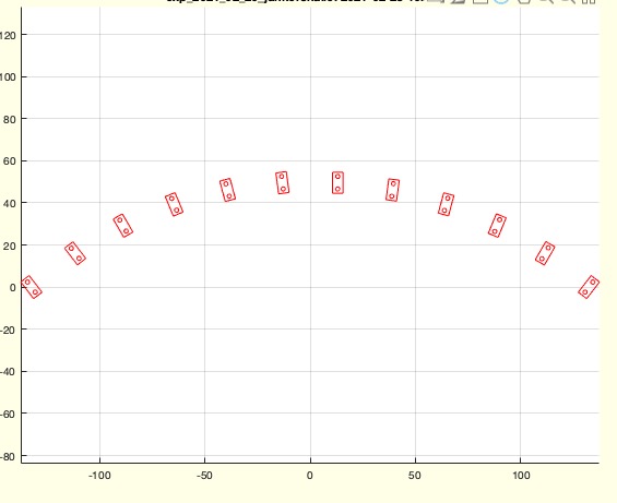 | % CPLcopypatternTL(CPL,TL,dw) - copies a CPL at positions of a PL % (by Tim Lueth, VLFL-Lib, 2021-FEB-28 as class: CLOSED POLYGON LISTS) % % Introduced first in SolidGeometry 5.1 % % See also: TLofPL, CPLcirclesofPL, SGpatternRotz, CPLcopypattern, % CPLcopypatternPL, SGpatternXYZ, CPLcopyradial % % CPLN=CPLcopypatternTL(CPL,TL,[dw]) % === INPUT PARAMETERS === % CPL: CPL to copy (nx2) % TL: array of transformation matrices such from TLofPL % dw: optional turing angle or turning array [nx1]; default is 0 % === OUTPUT RESULTS ====== % CPLN: Final CPL [nx2] % % EXAMPLE: % CPLcopypatternPL(PLcircle(1),20*rand(10,2)) % CPLcopypatternPL(PLcircle(1,4),20*rand(10,2),pi/10) % % See also: TLofPL, CPLcirclesofPL, SGpatternRotz, CPLcopypattern, % CPLcopypatternPL, SGpatternXYZ, CPLcopyradial % % % Copyright 2021 Tim C. Lueth |
TLofPL(PL,usem,nonc,z)- returns transformation frames for a PL |
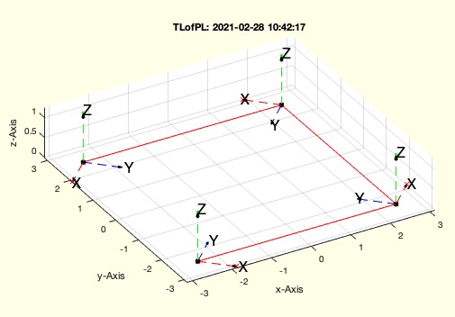 | % TLofPL(PL,usem,nonc,z) - returns transformation frames for a PL % (by Tim Lueth, VLFL-Lib, 2021-FEB-28 as class: KINEMATICS AND FRAMES) % % For creating TL lists of hust copyes of a frame use TcopyVLez % Much simpler fnctn for 2D cases than TLofCVL % The orientation of the x-axis is always the direction of the next edge % The orientation of the z-axis is always [0 0 1] % (Status of: 2021-02-28) % % Introduced first in SolidGeometry 5.1 % % See also: TcopyVLez, TLofCVL, VLdistance % % [TL2,TL3]=TLofPL(PL,[usem,nonc,z]) % === INPUT PARAMETERS === % PL: Point list % usem: if true; the mean direction vector is used; default is false % nonc: % z: z value for T3 cases; default is 0 % === OUTPUT RESULTS ====== % TL2: [3x3x n] 2D HT matrix array % TL3: [4x4x n] 3D HT matrix array % % See also: TcopyVLez, TLofCVL, VLdistance % % % Copyright 2021-2022 Tim C. Lueth |
SGjunkerhallpart(h,t,a,w,r,LL)- creates a part for a junker hall |
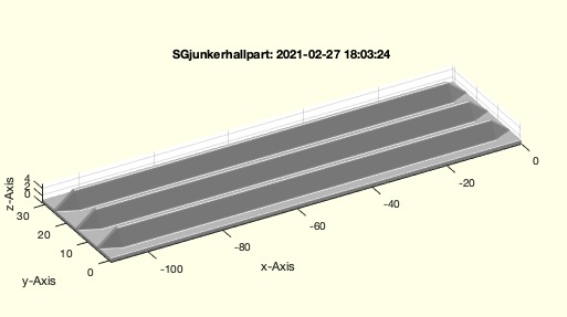 | % SGjunkerhallpart(h,t,a,w,r,LL) - creates a part for a junker hall % (by Tim Lueth, VLFL-Lib, 2021-FEB-26 as class: MODELING PROCEDURES) % % parameter will change until release % (Status of: 2021-02-27) % % Introduced first in SolidGeometry 5.1 % % See also: PLjunkerhallpart % % SG=SGjunkerhallpart([h,t,a,w,r,LL]) % === INPUT PARAMETERS === % h: list of sections; default is [5 10 10 5] % t: radius of impression; default is [0 4] % a: alpha for impressipm; default i pi/5 % w: wall thickness; default is t(2)/4 % r: radius for breaking edges; default is 0.5 % LL: [a b] straight length an ramp length % === OUTPUT RESULTS ====== % SG: Solid geometry % % EXAMPLE: % close all; SGjunkerhallpart([5 10 5],[0 4],'','',0); % % See also: PLjunkerhallpart % % % Copyright 2021 Tim C. Lueth |
PLjunkerhallpart(h,t,a,w,r)- creates a profile of a pressed profile |
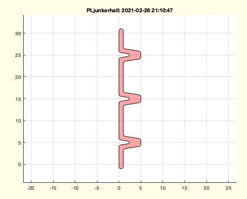 | % PLjunkerhallpart(h,t,a,w,r) - creates a profile of a pressed profile % (by Tim Lueth, VLFL-Lib, 2021-FEB-26 as class: CLOSED POLYGON LISTS) % % may be by chance, this fnctn is very similar to PLpinring % Thanks to Dr. Joachim Weber and Dr. Joram Tutsch for the reference to % these 100 years old structures, which also became the basis for the % all-metal aircraft. % (Status of: 2021-02-27) % % Introduced first in SolidGeometry 5.1 % % See also: PLpinring % % [CPL,CPL2]=PLjunkerhallpart([h,t,a,w,r]) % === INPUT PARAMETERS === % h: list of sections; default is [5 10 10 5] % t: radius of impression; default is [0 4] % a: alpha for impressipm; default i pi/10 % w: wall thickness; default is r(2)/4 % r: radius for breaking edges; default is 0.5 % === OUTPUT RESULTS ====== % CPL: CPL of profile to extrude % CPL2: CPL of profile at the tips % % EXAMPLE: % PLjunkerhallpart([5 10 10 5],[0 4],pi/10,1,0.5) % PLjunkerhallpart([5 10 10 5],[0 4],pi/3,1,0.5); % % See also: PLpinring % % % Copyright 2021 Tim C. Lueth |
existvolume(vname)- returns the full path of a volume's diretory if this volume exists i.e. it is mounted |
 | % existvolume(vname) - returns the full path of a volume's diretory if this volume exists i.e. it is mounted % (by Tim Lueth, VLFL-Lib, 2021-FEB-26 as class: FILE HANDLING) % % if a cell list of volume names is used, the first exisiting volume % directory is returned (Status of: 2021-02-26) % % Introduced first in SolidGeometry 5.1 % % See also: desktopshadow % % dname=existvolume([vname]) % === INPUT PARAMETERS === % vname: volume title % === OUTPUT RESULTS ====== % dname: matlab path to volume dir; ends always with filesep % % EXAMPLE: % existvolume('PLATTE LUETH ALL') % existvolume({'PLATTE LUETH ALL2','PLATTE LUETH ALL4','PLATTE LUETH ALL'}) % % See also: desktopshadow % % % Copyright 2021 Tim C. Lueth |