ELseparate(EL,jv)- reorders the edge list (triangle, tetrahedron) to individual polygons, surfaces, solids |
 | % ELseparate(EL,jv) - reorders the edge list (triangle, tetrahedron) to individual polygons, surfaces, solids % (by Tim Lueth, VLFL-Lib, 2014-DEZ-25 as class: AUXILIARY PROCEDURES) % % In fact, just calls ELorder! % All edges, facets, tetrahedrons of a solid use the same points after % using SGshort or SGcat. Therefor all tetrahedrons are linked by common % surfaces, surfaces are linked by common edges, edges are linked by % common points. This fnctns groups linked tetrahedrons, surfaces or % edges by using three, two, one common points. By an additional % parameter, it is possible ti chance this method. % ELorder (FL,2) connects facets that have a common edge! (default) % ELorder (FL,1) connects facets that have just one common points! % ELorder (FL,3) connects facets that have the same three common points! % (Status of: 2018-08-26) % % Introduced first in SolidGeometry 2.0 % % See also: ELorder, FLseparate, TLseparate, SGshort, SGcat % % [ELN,SIL]=ELseparate(EL,[jv]) % === INPUT PARAMETERS === % EL: edge list/facet list/tetrahedron list consisting of several solids % jv: optional number of common vertices that define a connection; % default is size(EL,2)-1 % === OUTPUT RESULTS ====== % ELN: Reordered Edge List % SIL: Sorted Index List % % EXAMPLE: Three methods to separate a tetrahedron % SGtetramesh(SGsample(25)); [~,VL,FL,TR]=SGtetramesh(SGsample(25)); EL=ELofFL(FL); % tic; [~,n]=ELseparate(EL), toc % % See also: ELorder, FLseparate, TLseparate, SGshort, SGcat % % % Copyright 2014-2018 Tim C. Lueth |
ELorder(EL,jv)- reorders the edge list (triangle, tetrahedron) to individual polygons, surfaces, solids |
 | % ELorder(EL,jv) - reorders the edge list (triangle, tetrahedron) to individual polygons, surfaces, solids % (by Tim Lueth, VLFL-Lib, 2014-DEZ-25 as class: AUXILIARY PROCEDURES) % % Equivalent to TRorder or SGorder but on edge level (in fact works with % all index lists). Improved in comparision with VLFLseparate. % All edges,facets,tetrahedrons of a solid use the same points. In case % that a solid geometry can be separated into several independent solids, % the given list here is ordered and in addition a list with starting % rows and end rows in the returned list is returned. % - For edges, one common point defines the attachment % - For facets, two common points define the attachment % - For tetrahedrons, three common points define the attachment % Anyway, exceptions are possible by the second input parameter % ELorder does not use the fnctn neighbors (Status of: 2018-08-25) % % Introduced first in SolidGeometry 2.0 % % See also: ELorder, FLorder, FLseparate, TRorder, SGorder, SGseparate, % graphofEL % % [ELN,SIL]=ELorder(EL,[jv]) % === INPUT PARAMETERS === % EL: edge list/facet list/tetrahedron list consisting of several solids % jv: common vertices that define a connection; default is size(EL,2)-1 % === OUTPUT RESULTS ====== % ELN: ordered edge list/facet list/tetrahedron list of several solids % SIL: Solid index list (start and end-row) in returned list % % EXAMPLE: Separate the surface of SGsample(8) and SGsample(9) % SG=SGsample(8); % TR3=triangulation(SG.FL,SG.VL); % FEL=featureEdges(TR3,0.001); % [a,b]=ELorder(FEL); b % % See also: ELorder, FLorder, FLseparate, TRorder, SGorder, SGseparate, % graphofEL % % % Copyright 2014-2019 Tim C. Lueth |
TLseparate(TL,jv)- reorders the edge list (triangle, tetrahedron) to individual polygons, surfaces, solids |
 | % TLseparate(TL,jv) - reorders the edge list (triangle, tetrahedron) to individual polygons, surfaces, solids % (by Tim Lueth, VLFL-Lib, 2014-DEZ-25 as class: AUXILIARY PROCEDURES) % % In fact, just calls ELorder! % All edges, facets, tetrahedrons of a solid use the same points after % using SGshort or SGcat. Therefor all tetrahedrons are linked by common % surfaces, surfaces are linked by common edges, edges are linked by % common points. This fnctns groups linked tetrahedrons, surfaces or % edges by using three, two, one common points. By an additional % parameter, it is possible ti chance this method. % ELorder (FL,2) connects facets that have a common edge! (default) % ELorder (FL,1) connects facets that have just one common points! % ELorder (FL,3) connects facets that have the same three common points! % (Status of: 2018-08-26) % % Introduced first in SolidGeometry 2.0 % % See also: ELorder, ELseparate, FLseparate, SGshort, SGcat % % [TLN,SIL]=TLseparate(TL,[jv]) % === INPUT PARAMETERS === % TL: edge list/facet list/tetrahedron list consisting of several solids % jv: optional number of common elements that define a connection; % default is size(EL,2)-1 % === OUTPUT RESULTS ====== % TLN: Reordered Edge List % SIL: Sorted Index List % % EXAMPLE: Three methods to separate a tetrahedron % SGtetramesh(SGsample(25)); [~,VL,FL,TR]=SGtetramesh(SGsample(25)); % tic; [~,n]=TLseparate(TR.ConnectivityList), toc % % See also: ELorder, ELseparate, FLseparate, SGshort, SGcat % % % Copyright 2014-2018 Tim C. Lueth |
FLseparate(FL,jv)- reorders the edge list (triangle, tetrahedron) to individual polygons, surfaces, solids |
 | % FLseparate(FL,jv) - reorders the edge list (triangle, tetrahedron) to individual polygons, surfaces, solids % (by Tim Lueth, VLFL-Lib, 2014-DEZ-25 as class: AUXILIARY PROCEDURES) % % In fact, just calls ELorder! % All edges, facets, tetrahedrons of a solid use the same points after % using SGshort or SGcat. Therefor all tetrahedrons are linked by common % surfaces, surfaces are linked by common edges, edges are linked by % common points. This fnctns groups linked tetrahedrons, surfaces or % edges by using three, two, one common points. By an additional % parameter, it is possible ti chance this method. % ELorder (FL,2) connects facets that have a common edge! (default) % ELorder (FL,1) connects facets that have just one common points! % ELorder (FL,3) connects facets that have the same three common points! % (Status of: 2018-08-26) % % Introduced first in SolidGeometry 2.0 % % See also: ELorder, ELseparate, TLseparate, SGshort, SGcat % % [FLN,SIL]=FLseparate(FL,[jv]) % === INPUT PARAMETERS === % FL: edge list/facet list/tetrahedron list consisting of several solids % jv: optional number of common vertices that define a connection; % default is size(EL,2)-1 % === OUTPUT RESULTS ====== % FLN: Reordered Facet List % SIL: Sorted Index List % % EXAMPLE: Three methods to separate a tetrahedron % SGtetramesh(SGsample(25)); [~,VL,FL,TR]=SGtetramesh(SGsample(25)); % tic; [~,n]=FLseparate(FL), toc % % See also: ELorder, ELseparate, TLseparate, SGshort, SGcat % % % Copyright 2014-2018 Tim C. Lueth |
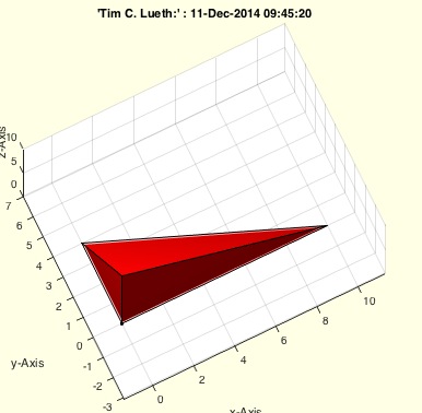
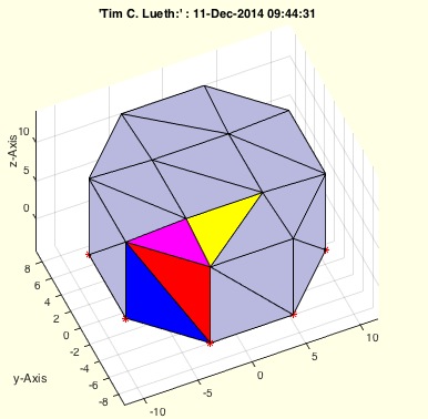
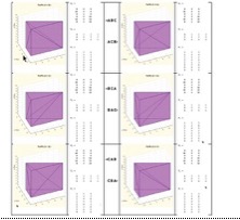
exp_2014_12_25- EXPERIMENT to show different feature edges, facets, and tetrahedrons of a SGsample |
 | % exp_2014_12_25 - EXPERIMENT to show different feature edges, facets, % and tetrahedrons of a SGsample % (by Tim Lueth, VLFL-Lib, 2014-DEZ-25 as class: EXPERIMENTS) % % exp_2014_12_25 % |
VLFLofTR(TR)- returns the freeboundary surface of a tetrahedron or the surface of a triangulation |
 | % VLFLofTR(TR) - returns the freeboundary surface of a tetrahedron or the % surface of a triangulation % (by Tim Lueth, VLFL-Lib, 2014-DEZ-22 as class: TETRAHEDRONS) % % Returns the surface model (VL,FL) from a tetrahedron volume model by % using freeBoundary. If the triangulation is a surface model, the % ConnectivityList is returned. (Status of: 2014-12-22) % % [VL,FL]=VLFLofTR(TR) % === INPUT PARAMETERS === % TR: Triangulation (nx4 or nx3) % === OUTPUT RESULTS ====== % VL: Vertex List (Point List) % FL: Facet List (ConnectivityList or freeBoundary) % % EXAMPLE: % [VL,FL]=VLFLofTR(exp_2014_12_23 (SGsample(16))); close all; VLFLfigure; % view(-30,30); VLFLplots(VL,FL); % |
exp_2014_12_23(SG)- EXPERIMENT returns a tetrahedron triangulation from a surface triangulation |
 | % exp_2014_12_23(SG) - EXPERIMENT returns a tetrahedron triangulation % from a surface triangulation % (by Tim Lueth, VLFL-Lib, 2014-DEZ-22 as class: TETRAHEDRONS) % % This is the experiment to implement TRofSG (Status of: 2014-12-22) % % TR=exp_2014_12_23(SG) % === INPUT PARAMETERS === % SG: Solid Geometry (VL,FL) % === OUTPUT RESULTS ====== % TR: Tetrahedron triangulation % |
exp_2014_12_22- |
 | % exp_2014_12_22 - % (by Tim Lueth, VLFL-Lib, 2014-DEZ-22 as class: EXPERIMENTS) % % exp_2014_12_22 % |
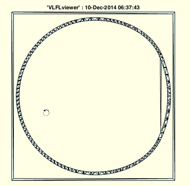
PLELofFeatureEdges(TR,alpha)- returns sorted closed polygon edge lists of the feature edges of a solid |
 | % PLELofFeatureEdges(TR,alpha) - returns sorted closed polygon edge lists of the feature edges of a solid % (by Tim Lueth, VLFL-Lib, 2014-DEZ-21 as class: SURFACES) % % fast and powerful fnctn that links the feature edges to closed polygon % edge lists with a defined normal vector % Uses: TRfeatureEdgeFacets (Status of: 2017-04-05) % % See also: FLfeatureEdgeSurface, FLfeatureEdgeSurface2, % PLELofFeatureEdges2, TRfeatureEdgeFacets, FEplot % % [ELFL,SIL]=PLELofFeatureEdges(TR,[alpha]) % === INPUT PARAMETERS === % TR: surface triangulation for feature edges % alpha: feature edge angle % === OUTPUT RESULTS ====== % ELFL: % SIL: Selected Index List for % % EXAMPLE: Recreate the polygons of a % closeall; SG=SGsample(16); % TR=triangulation(SG.FL,SG.VL); % VLFLfigure; [ELFL,SIL]=PLELofFeatureEdges (TR); % |
TRfeatureEdgeFacets(TR,alpha)- returns the list of facets linked to edges of the featureEdges |
 | % TRfeatureEdgeFacets(TR,alpha) - returns the list of facets linked to edges of the featureEdges % (by Tim Lueth, VLFL-Lib, 2014-DEZ-21 as class: SURFACES) % % EdgelistFacetlist % [edgestart (1) edgeend (2) facetattached (3) normalvectoroffacet (4:6)] % Quite frustrating. This fnctn took 30 minutes after 40 minutes sport % after several days unsuccessful programming exp_2014_12_16. (Status of: % 2017-04-05) % % See also: FEplot, FLfeatureEdgeSurface, FLfeatureEdgeSurface2, % PLELofFeatureEdges, PLELofFeatureEdges2, FEplot % % [ELFL]=TRfeatureEdgeFacets(TR,[alpha]) % === INPUT PARAMETERS === % TR: triangulation nx3 % alpha: filterangle for featureEdges % === OUTPUT RESULTS ====== % [ELFL]: % |
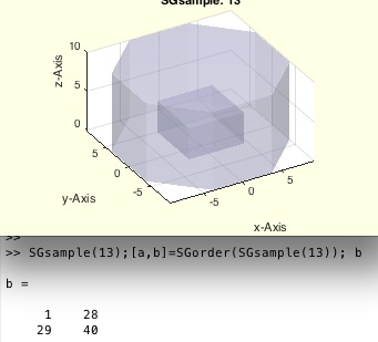
SGorder(SG)- reorders the triangle facets to individual solids |
 | % SGorder(SG) - reorders the triangle facets to individual solids % (by Tim Lueth, VLFL-Lib, 2014-DEZ-20 as class: AUXILIARY PROCEDURES) % % Equivalent to TRorder but on facet level (one day may be fused). % Improved in comparision with VLFLseparate. % % All surface facets of a solid use the same points. In case that a solid % geometry has a facet list that in fact is separated into several % solids, this fnctns reorders the facet list to connected surfaces and % returns also a list with starting facet and end facet of the list. % (Status of: 2017-02-21) % % See also: ELorder, FLorder, FLseparate, TRorder, SGseparate % % [SG,SIL]=SGorder(SG) % === INPUT PARAMETERS === % SG: Solid geometry whose facet list consisting of several solids % === OUTPUT RESULTS ====== % SG: Solid geometry whose facet list consisting of several solids % SIL: Solid index list (start and end-facet) in facet list % % EXAMPLE: Separate the surface of SGsample(13) % SGsample(13);[a,b]=SGorder(SGsample(13)); b % |
ELselect(EL,i)- return all edges from an edge list start start or end with ONE SINGLE index |
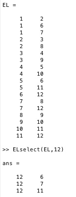 | % ELselect(EL,i) - return all edges from an edge list start start or end with ONE SINGLE index % (by Tim Lueth, VLFL-Lib, 2014-DEZ-19 as class: AUXILIARY PROCEDURES) % % fast efficient single row fnctn (makro) (Status of: 2021-03-13) % % Introduced first in SolidGeometry 2.0 % % See also: FLselect, FLofVLFLvi, FLofVLFLfi % % ELi=ELselect(EL,i) % === INPUT PARAMETERS === % EL: Edge list % i: vertex index % === OUTPUT RESULTS ====== % ELi: Edge list from index. ELi(:,1) is always i % % See also: FLselect, FLofVLFLvi, FLofVLFLfi % % % Copyright 2014-2021 Tim C. Lueth |
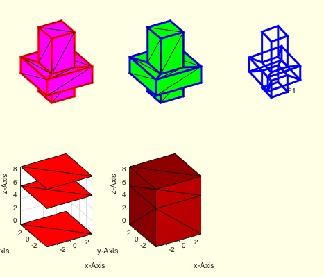
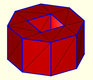
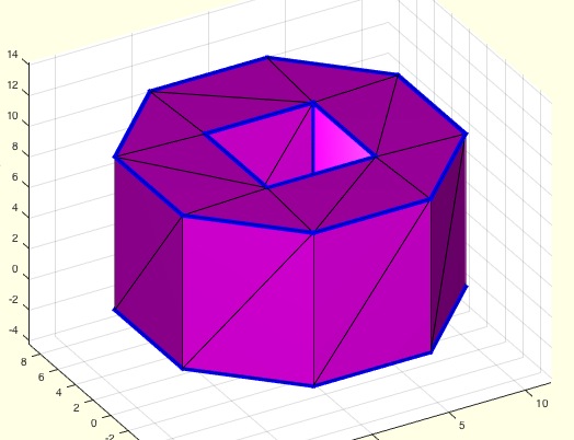
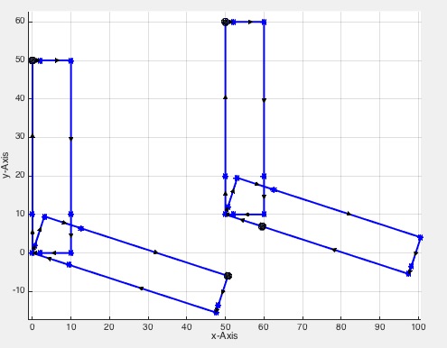
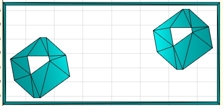
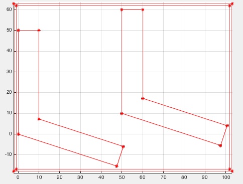
exp_2014_12_16- PUBLISHABLE EXPERIMENT to understand the power of featureEdges for the reconstruction of solids |
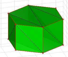 | % exp_2014_12_16 - PUBLISHABLE EXPERIMENT to understand the power of % featureEdges for the reconstruction of solids % (by Tim Lueth, VLFL-Lib, 2014-DEZ-16 as class: EXPERIMENTS) % % 1. This experiment starts with the construction of a surface model of a % n-edge polygon, extruded to a n-edge cylinder. It consists of a vertex % list and a surface facet list (VL,FL). % 2. Next we create a tetrahedron delaunay-triangulation based on the 3D % vertex list (TR). The facets created here does not have to be the same % as of the ones of the first surface generation. Could be but not have % to. % 3. We take the feature edge list which as to be the same for both % representations. Even if the facets were different since there is no % unique/bijective representation of a surface by facets, the feature % edge list must be the same constraint lines of the surface. % 4. Next we try to reconnect the edge lists to planar surfaces by % finding closed polygon lines aorund surfaces with the same normal % vector. This is done by the new procedure TRselect that has the same % job as VLELselect. Nevertheless here we can use the knowledge on the % normal vectors of the facet. (Status of: 2014-12-26) % % exp_2014_12_16 % |
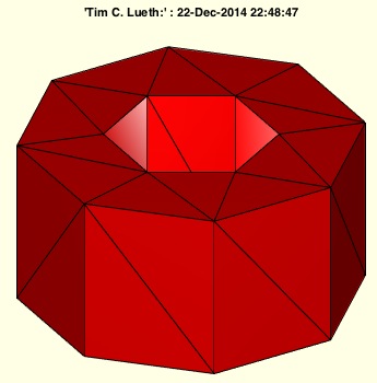
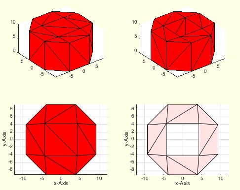
exp_2014_12_13c(n,n2)- Tetrahedron solids based on closed polygon list processing |
 | % exp_2014_12_13c(n,n2) - Tetrahedron solids based on closed polygon list % processing % (by Tim Lueth, VLFL-Lib, 2014-DEZ-14 as class: EXPERIMENTS) % % dte=exp_2014_12_13c creates first an outside n-point polygon with an % optional m-point polygon insisde, depending on the input parameters. % Then these close polygon lines (CPLs) should be converted into a % tetrahedron triangulation of an extrusion of the CPL with the height z. % For this purpose a frame is created outside of the polygon first. Then % contour by contour a delaunay triangulation is created. % % The concept of this procedure is similar to CLPrecontour but it works % on tetrahedron solids. % While facet based surfaces are enclosed and described by polygons % (cw,ccw) % terahedron based solids are enclosed and described by surfaces. % In this procedure we create tetrahedron by simple 2.5D extrusion of % CPLs and add or remove the inner parts. % % % Created after exp_2014_12_14 the same day later. (Status of: 2014-12-19) % % dte=exp_2014_12_13c([n,n2]) % === INPUT PARAMETERS === % n: Number of points of the outer polygon, default is 4 % n2: Optional number of points of the inner polygon, default is 0 % === OUTPUT RESULTS ====== % dte: resulting tetrahedron triangulation % |
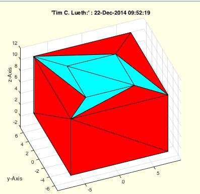
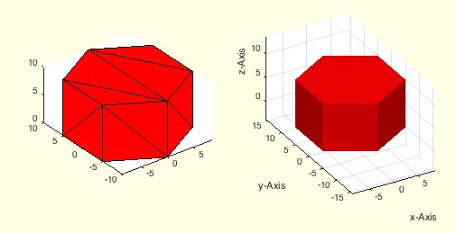
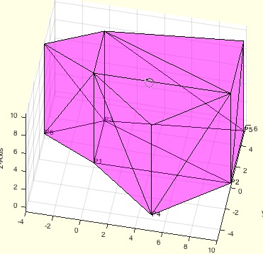
exp_2014_12_14(n,n2)- Experiment to show the structure of Delaunay Tesselation of Tetrahedron |
 | % exp_2014_12_14(n,n2) - Experiment to show the structure of Delaunay % Tesselation of Tetrahedron % (by Tim Lueth, VLFL-Lib, 2014-DEZ-13 as class: EXPERIMENTS) % % TR=exp_2014_12_14([n,n2]) % === INPUT PARAMETERS === % n: Number of edges of an out circle % n2: Optional number of edges of an inner circle; default 0 % === OUTPUT RESULTS ====== % TR: % % EXAMPLE: exp_2014_12_14 (10,4) % |
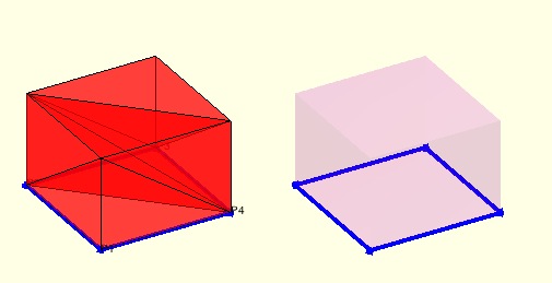
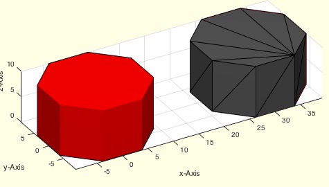
exp_2014_12_13- PUBLISHABLE EXPERIMENT shows the difference between triangulation and delaunayTriangulation |
 | % exp_2014_12_13 - PUBLISHABLE EXPERIMENT shows the difference between % triangulation and delaunayTriangulation % (by Tim Lueth, VLFL-Lib, 2014-DEZ-12 as class: EXPERIMENTS) % % This procedure shows the difference between triangulation and % delaunayTriangulation (Status of: 2014-12-13) % % exp_2014_12_13 % |
exp_2014_12_12- PUBLISHABLE EXPERIMENT shows the difference between triangulation and delaunayTriangulation |
 | % exp_2014_12_12 - PUBLISHABLE EXPERIMENT shows the difference between % triangulation and delaunayTriangulation % (by Tim Lueth, VLFL-Lib, 2014-DEZ-11 as class: EXPERIMENTS) % % This procedure shows the difference between triangulation and % delaunayTriangulation (Status of: 2014-12-12) % % exp_2014_12_12 % |
exp_2014_12_11- PUBLISHABLE EXPERIMENT for tetrahedron generation |
 | % exp_2014_12_11 - PUBLISHABLE EXPERIMENT for tetrahedron generation % (by Tim Lueth, VLFL-Lib, 2014-DEZ-10 as class: EXPERIMENTS) % % exp_2014_12_11 % |
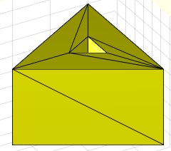
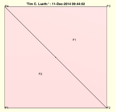
exp_2014_12_10(XFL)- EXPERIMENT just shows for a prismatic object based on a traingle the evolving tetrahedron |
 | % exp_2014_12_10(XFL) - EXPERIMENT just shows for a prismatic object % based on a traingle the evolving tetrahedron % (by Tim Lueth, VLFL-Lib, 2014-DEZ-10 as class: EXPERIMENTS) % % Palma Cala Major - Using % TL=TLofFL([3 1 2],size(PL,1)) and % FL=FLofTetrahedron(TL) (Status of: 2014-12-10) % % exp_2014_12_10([XFL]) % === INPUT PARAMETERS === % XFL: Facet for the triangle; default is [3 1 2] % % EXAMPLE: Just try % exp_2014_12_10 % |
VLTLplot(VL,TL,c,so)- plots a tetrahedron list as one volume or as separated tetrahedrons |
 | % VLTLplot(VL,TL,c,so) - plots a tetrahedron list as one volume or as separated tetrahedrons % (by Tim Lueth, VLFL-Lib, 2014-DEZ-09 as class: TETRAHEDRONS) % % uses tetramesh to print all tetrahedrons in one step. % Each tetrahedron is plotted seperately (slow) (Status of: 2017-02-08) % % See also: VLFLplot, SGplot, TRplot, VLFLplot4 % % h=VLTLplot(VL,TL,[c,so]) % === INPUT PARAMETERS === % VL: Vertex list % TL: Tetrahedrons list % c: color % so: true = single handle, false = separated handles % === OUTPUT RESULTS ====== % h: handles to graphics object % |
exp_2014_12_09- just shows for a prismatic object based on a traingle the tetrahedron |
 | % exp_2014_12_09 - just shows for a prismatic object based on a traingle % the tetrahedron % (by Tim Lueth, VLFL-Lib, 2014-DEZ-09 as class: EXPERIMENTS) % % Palma Cala Major (Status of: 2014-12-09) % % exp_2014_12_09 % |
exp_2014_12_08(XFL)- EXPERIMENT just shows for a prismatic object based on a traingle the evolving tetrahedron |
 | % exp_2014_12_08(XFL) - EXPERIMENT just shows for a prismatic object % based on a traingle the evolving tetrahedron % (by Tim Lueth, VLFL-Lib, 2014-DEZ-08 as class: EXPERIMENTS) % % Palma Cala Major - Using % TL=TLofFL([3 1 2],size(PL,1)) and % FL=FLofTetrahedron(TL) (Status of: 2014-12-10) % % exp_2014_12_08([XFL]) % === INPUT PARAMETERS === % XFL: Facet for the triangle; default is [3 1 2] % % EXAMPLE: Just try % exp_2014_12_08 ([ 1 2 3]) % |
exp_2014_12_07(CPL);- EXPERIMENT Extrude a CPL into a tetrahedron representation |
 | % exp_2014_12_07(CPL); - EXPERIMENT Extrude a CPL into a tetrahedron % representation % (by Tim Lueth, VLFL-Lib, 2014-DEZ-06 as class: EXPERIMENTS) % % Work in progress, Should use the slicing result of exp_2014_12_06 % Not finished (Status of: 2014-12-10) % % [PL,FL]=exp_2014_12_07([CPL]); % === INPUT PARAMETERS === % CPL): Closed polygon list % === OUTPUT RESULTS ====== % PL: Point list % FL: Facet list % |
TLofFL(FL,n)- converts a planar facet list into a 2.5 tetrahedron list |
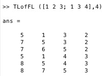 | % TLofFL(FL,n) - converts a planar facet list into a 2.5 tetrahedron list % (by Tim Lueth, VLFL-Lib, 2014-DEZ-06 as class: TETRAHEDRONS) % % Work in progress, does not work correctly for more than 1 triangle % (Status of: 2014-12-06) % % TL=TLofFL(FL,[n]) % === INPUT PARAMETERS === % FL: Facet list % n: number of points in vertex list % === OUTPUT RESULTS ====== % TL: Tetrahedron list % |
FLshift(FL)- returns a shifted and ordered facet list |
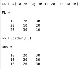 | % FLshift(FL) - returns a shifted and ordered facet list % (by Tim Lueth, VLFL-Lib, 2014-DEZ-06 as class: AUXILIARY PROCEDURES) % % The facet list is rotated line by line so that the smallest vertex % index is in the left column. % % In contrast to FLorder, the rows are not sorted afterwards. (Status of: % 2015-08-05) % % FL=FLshift(FL) % === INPUT PARAMETERS === % FL: Original facet list % === OUTPUT RESULTS ====== % FL: Final facet list % % EXAMPLE: % FL=[10 20 30; 30 10 20; 20 30 10] % FL=[FL*1.5;FL] % FLshift(FL) % |
TRplot(TR,c,fb)- plots a tetrahedron triangulation similar to SGplot |
 | % TRplot(TR,c,fb) - plots a tetrahedron triangulation similar to SGplot % (by Tim Lueth, VLFL-Lib, 2014-DEZ-06 as class: TETRAHEDRONS) % % more or less: tetramesh(TR4) % % (Status of: 2017-02-08) % % See also: VLFLplot, SGplot, VLTLplot, VLFLplot4 % % h=TRplot(TR,[c,fb]) % === INPUT PARAMETERS === % TR: Tetrahedron % c: color % fb: true=freeBoundary [default], false=tetrahedrons, % === OUTPUT RESULTS ====== % h: handles % % EXAMPLE: Show the convex hull % A=SGsample(17) % TR=delaunayTriangulation(A.VL); % TRplot(TR) % |
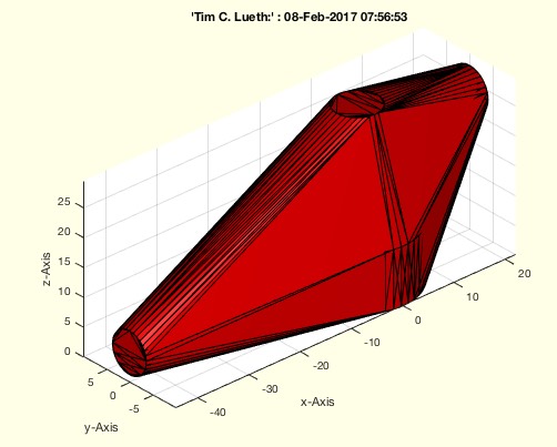
TRofCPLz (CPL,z)- returns a valid tetrahedron representation of a solid |
 | % TRofCPLz (CPL,z) - returns a valid tetrahedron representation of a solid % (by Tim Lueth, VLFL-Lib, 2014-DEZ-06 as class: TETRAHEDRONS) % % This procedures is an extension of the first ideas with DTofPLELz % (2014-01-14). This time the appraoch is based on the concepts Closed % Polygon Lines (CPL) and Triangulation (TR) wich are both available in % Matlab 2014b. (Status of: 2014-12-06) % % TRofCPLz(CPL,z) % === INPUT PARAMETERS === % CPL: Closed polygon list for base plate % z: solid height in z-direction % |
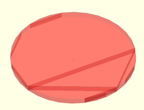
CPLnonmanifold(CPL)- true if a point is used twice in the CPL or PL |
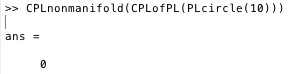 | % CPLnonmanifold(CPL) - true if a point is used twice in the CPL or PL % (by Tim Lueth, VLFL-Lib, 2014-DEZ-06 as class: AUXILIARY PROCEDURES) % % Slow, try to avoid if possbile (Status of: 2014-12-06) % % nm=CPLnonmanifold(CPL) % === INPUT PARAMETERS === % CPL: closed polygon list % === OUTPUT RESULTS ====== % nm: true if non manifold points % % EXAMPLE: % CPLnonmanifold(CPLofPL(PLcircle(10))) % |
CPLofPL(PL)- appends the first point to a point list of required |
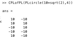 | % CPLofPL(PL) - appends the first point to a point list of required % (by Tim Lueth, VLFL-Lib, 2014-DEZ-06 as class: AUXILIARY PROCEDURES) % % The last point of a CPL has to be the first point. % Slow, please try to avoid if possibile (Status of: 2019-06-19) % % Introduced first in SolidGeometry 2.0 % % See also: PLofCPL, CPLofPLcontour % % CPL=CPLofPL(PL) % === INPUT PARAMETERS === % PL: point list % === OUTPUT RESULTS ====== % CPL: closed polygon list % % See also: PLofCPL, CPLofPLcontour % % % Copyright 2014-2019 Tim C. Lueth |
exp_2014_12_06(z)- PUBLISHABLE experiment to show the result of different slicing techniques |
 | % exp_2014_12_06(z) - PUBLISHABLE experiment to show the result of % different slicing techniques % (by Tim Lueth, VLFL-Lib, 2014-DEZ-06 as class: EXPERIMENTS) % % Does work currently only with correct sample files (no errors in the % VL/FL) (Status of: 2014-12-06) % % CPL=exp_2014_12_06([z]) % === INPUT PARAMETERS === % z: z-coordinate for slicing plane % === OUTPUT RESULTS ====== % CPL: Resulting contour polygon list % |
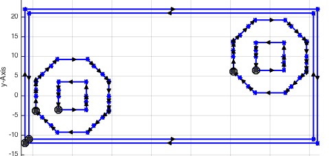
CPLrecontour(CPL,frm)- returns a contour list for a sliced/cutted object |
 | % CPLrecontour(CPL,frm) - returns a contour list for a sliced/cutted object % (by Tim Lueth, VLFL-Lib, 2014-DEZ-05 as class: ANALYTICAL GEOMETRY) % % A given CPL (closed polygon list, contains NaN) is ordered by x and y % values first. Then each polygon is analyzed regarding the clockwise % direction (cw/ccw). Then all polygons are united or subtracted % depending on their direction. To have a defined start point, a frame is % generated that is the maximum outside border of the polygons inside. By % a second parameter it is possible to delete the frame from the % resulting CPL. % The resulting list is a always VALID closed polygon list. % % (Status of: 2018-08-27) % % Introduced first in SolidGeometry 2.0 % % See also: CPLsplitpoints, CPLrepair % % NPL=CPLrecontour(CPL,[frm]) % === INPUT PARAMETERS === % CPL: Closed polygon list, contains NaN % frm: true=frame, false=no frame % === OUTPUT RESULTS ====== % NPL: resulting closed polygon list (with our without a frame) % % See also: CPLsplitpoints, CPLrepair % % % Copyright 2014-2018 Tim C. Lueth |
exp_2014_12_04- PUBLISHABLE EXPERIMENT SIMILAR TO 2014_12_05 but for STL Files |
 | % exp_2014_12_04 - PUBLISHABLE EXPERIMENT SIMILAR TO 2014_12_05 but for % STL Files % (by Tim Lueth, VLFL-Lib, 2014-DEZ-05 as class: EXPERIMENTS) % % Work in progress % This experiment was used to develop the CPLrecontour procedure an to % see the effect of attached edges, non manifold points and non manifold % edges. By reading in different STL files is becomes obvious that % corrupted STL files are a serious problem for any slicer. (Status of: % 2014-12-10) % % exp_2014_12_04 % |
CPLremstraight(CPL)- removes points from straight lines in all contours of CPL |
 | % CPLremstraight(CPL) - removes points from straight lines in all contours of CPL % (by Tim Lueth, VLFL-Lib, 2014-DEZ-05 as class: AUXILIARY PROCEDURES) % % ======================================================================= % OBSOLETE (2017-07-13) - USE FAMILY 'CVLremstraight' INSTEAD % ======================================================================= % % Splits non-manifold points(not edges), shift the contours to start with % minx/miny, order from left bottum to right up AND remove points that % are on a straight line. (Status of: 2014-12-26) % % Introduced first in SolidGeometry 2.0 % % See also: [ CVLremstraight ] ; VLremstraightCVL % % NPL=CPLremstraight(CPL) % === INPUT PARAMETERS === % CPL: Original closed polygon list (includes NaN) % === OUTPUT RESULTS ====== % NPL: CPL list: Splitted, shifted, and ordered list with only two points % for a straight line % % See also: [ CVLremstraight ] ; VLremstraightCVL % |
CPLorder(CPL,smax)- returns an xy ordered and shifted CPL |
 | % CPLorder(CPL,smax) - returns an xy ordered and shifted CPL % (by Tim Lueth, VLFL-Lib, 2014-DEZ-05 as class: AUXILIARY PROCEDURES) % % All polygons are now orderd from outside to inside, so that they can % processed one after another. % They ordered from minx/miny to maxx/maxy or in the opposite way. % (Status of: 2015-08-16) % % NCPL=CPLorder(CPL,[smax]) % === INPUT PARAMETERS === % CPL: Closed Polygon List (including NaN) % smax: max if true, min if false; default is false % === OUTPUT RESULTS ====== % NCPL: Ordered closed polygon list % |
CPLcircshift(PL,cl)- shifts & closes a PL. First point is [minx miny] |
 | % CPLcircshift(PL,cl) - shifts & closes a PL. First point is [minx miny] % (by Tim Lueth, VLFL-Lib, 2014-DEZ-05 as class: CLOSED POLYGON LISTS) % % Attention the length of the NPL can be increased to add the first point % as last point. % cl = false => CPL may be longer than PL % CL = true => CPL is PL if the input argument was PL % (Status of: 2018-08-27) % % Introduced first in SolidGeometry 2.0 % % See also: circshiftCPL % % [NPL,k]=CPLcircshift(PL,[cl]) % === INPUT PARAMETERS === % PL: Original PL or CPL % cl: constant length; default is false % === OUTPUT RESULTS ====== % NPL: Shifted and CPL % k: shiftindex % % See also: circshiftCPL % % % Copyright 2014-2019 Tim C. Lueth |
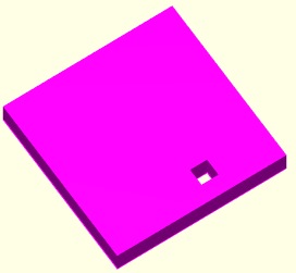
CPLsplitpoints(CPL)- Splits non manifold points in a CPL |
 | % CPLsplitpoints(CPL) - Splits non manifold points in a CPL % (by Tim Lueth, VLFL-Lib, 2014-DEZ-05 as class: AUXILIARY PROCEDURES) % % ======================================================================= % OBSOLETE (2018-11-19) - USE 'PLELofCPLsplitpoints' INSTEAD % ======================================================================= % % Sometimes as a result of slicing process, there are non manifold points % (joint points) of two closed CPLs. This is detected and corrected by % this procedure. If there are - after a slicing procedure - non manifold % edges in a plane, somebody made a mistake during the design. Non % manifold points in a plane can be resolved. Non manifold edge not by % this procedure. % Intellectual property: This can be used as copy protection for 3D print % protection. It is possible visualize but not possible to print. (Status % of: 2018-11-13) % % Introduced first in SolidGeometry 2.0 % % See also: [ PLELofCPLsplitpoints ] ; PLsplitpointsofCPL, CPLrecontour, % CPLrepair % % NPL=CPLsplitpoints(CPL) % === INPUT PARAMETERS === % CPL: Contour polygon list % === OUTPUT RESULTS ====== % NPL: Corrected Contour polygon list % % See also: [ PLELofCPLsplitpoints ] ; PLsplitpointsofCPL, CPLrecontour, % CPLrepair % % % Copyright 2014-2018 Tim C. Lueth |
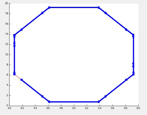
CPLisccw(CPL)- returns index list for CPL direction |
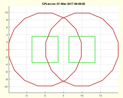 | % CPLisccw(CPL) - returns index list for CPL direction % (by Tim Lueth, VLFL-Lib, 2014-DEZ-05 as class: ANALYTICAL GEOMETRY) % % the same as ~ispolycw % This fnctn is unchanged and valid even with the new polyshape concept % (Status of: 2019-07-05) % % Introduced first in SolidGeometry 2.0 % % See also: CPLisccwinout, CPLsortinout, CPLisccwcorrected, CPLsetallcw % % [cwi,nani]=CPLisccw(CPL) % === INPUT PARAMETERS === % CPL: CPL % === OUTPUT RESULTS ====== % cwi: counter-clockwise index % nani: NAN-indices % % EXAMPLE: % CPLisccw(CPLsample(11)) % % See also: CPLisccwinout, CPLsortinout, CPLisccwcorrected, CPLsetallcw % % % Copyright 2014-2019 Tim C. Lueth |
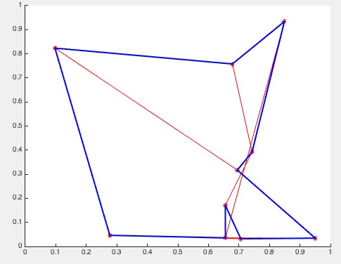
exp_2014_12_05- PUBLISHABLE EXPERIMENT for slicer reconstruction, analyzing non manifold problems |
 | % exp_2014_12_05 - PUBLISHABLE EXPERIMENT for slicer reconstruction, % analyzing non manifold problems % (by Tim Lueth, VLFL-Lib, 2014-DEZ-05 as class: EXPERIMENTS) % % Work in progress % This experiment was used to develop the CPLrecontour procedure an to % see the effect of attached edges, non manifold points and non manifold % edges. (Status of: 2014-12-05) % % exp_2014_12_05 % |
SGtrans(SG,T)- multi transformation modes for a solid geometry |
 | % SGtrans(SG,T) - multi transformation modes for a solid geometry % (by Tim Lueth, VLFL-Lib, 2014-DEZ-03 as class: ANALYTICAL GEOMETRY) % % Does currently not support a list of solids. % Combines SGytrans0, SGtrans1, SGtransP, SGtransR, SGtransT depending on % the transformation value % SGtrans(SG,0) % SGtrans(SG,1) % SGtrans(SG,[0 0 10] % SGtrans(SG,[0; 0 ;10]) % SGtrans(SG,rot(pi/3)) % SGtrans(SG,rot(pi/3,pi/2,0)) % SGtrans(SG,TofDPhiH(20,pi/6,10)) (Status of: 2017-08-23) % % Introduced first in SolidGeometry 2.0 % % See also: SGtrans0, SGtrans1, SGtransP, SGtransR, SGtransrelSG, % SGtransrelT, SGtransT % % [SG1,varargout]=SGtrans(SG,T) % === INPUT PARAMETERS === % SG: Solid Geometry % T: Transformation Value, Vector, or Matrix % === OUTPUT RESULTS ====== % [G1,varargout]=SGtrans(SG,T) % % if size(T,1)==1 && size(T,2)==1 % if T==0]: Transforms solid geometry % [G1,varargout]=SGtrans(SG,T) % % if size(T,1)==1 && size(T,2)==1 % if T==0]: % % See also: SGtrans0, SGtrans1, SGtransP, SGtransR, SGtransrelSG, % SGtransrelT, SGtransT % % % Copyright 2014-2017 Tim C. Lueth |
SGsample(Nr,T)- returns a solid geometry for sample bodies used for testing and experiments |
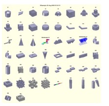 | % SGsample(Nr,T) - returns a solid geometry for sample bodies used for testing and experiments % (by Tim Lueth, VLFL-Lib, 2014-DEZ-03 as class: MODELING PROCEDURES) % % there are different solids in different structures that support the % test of different geometries: % random solids [1,2] % non manifold problems: [14,35,27:43] (Status of: 2018-11-02) % % Introduced first in SolidGeometry 2.0 % % See also: CPLsample, VLsample, PLsample, VLFLsample, CSGsample, % SGerrorsample, SGfischertechniksample, SGcmdsample, testfunctTL, % permutevector, CVLzsample % % [SG,FL]=SGsample([Nr,T]) % === INPUT PARAMETERS === % Nr: Nr of sample solid; default is show % T: Parameter for SGtrans (Value, Vector, Matrix) % === OUTPUT RESULTS ====== % SG: Solid geometry % FL: Facet point list wrt to SG.VL % % EXAMPLE: % SGsample % SGsample(5) % % See also: CPLsample, VLsample, PLsample, VLFLsample, CSGsample, % SGerrorsample, SGfischertechniksample, SGcmdsample, testfunctTL, % permutevector, CVLzsample % % % Copyright 2014-2021 Tim C. Lueth |
exp_2014_12_03- PUBLISHABLE EXPERIMENT for VLFL reconstuction |
 | % exp_2014_12_03 - PUBLISHABLE EXPERIMENT for VLFL reconstuction % (by Tim Lueth, VLFL-Lib, 2014-DEZ-03 as class: EXPERIMENTS) % % Work in progress % Uses SGsample(12,13,14,15) to generate a solid, slice it a cutting % plane and calculate the evolving contour (Status of: 2014-12-05) % % exp_2014_12_03 % |
PLrand(n,r,c)- returns a point list with random points |
 | % PLrand(n,r,c) - returns a point list with random points % (by Tim Lueth, VLFL-Lib, 2014-DEZ-02 as class: AUXILIARY PROCEDURES) % % mainly r*rand(n,2) but combined with PLsortC (Status of: 2017-01-05) % % See also: PLcircle, PLcircseg, PLevolvente, PLgear, PLhelix, PLkidney, % PLspiral, PLsquare, PLstar % % [PL,CPL]=PLrand([n,r,c]) % === INPUT PARAMETERS === % n: number of points; default is 10 % r: Radius; default is 10 % c: Center; default is [0 0] % === OUTPUT RESULTS ====== % PL: Point list nx2 (unsorted) % CPL: Point list nx2 (sorted as contour), not closed % % EXAMPLE: close all; % CPLplot(PLsortC(PLrand(20,10))); view(0,90); axis equal; % |
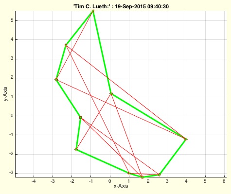
PLsortC(PL,d)- returns a point list that is sorted around its' center |
 | % PLsortC(PL,d) - returns a point list that is sorted around its' center % (by Tim Lueth, VLFL-Lib, 2014-DEZ-02 as class: AUXILIARY PROCEDURES) % % Uses VLsortC. All points are part of the resulting list. (Status of: % 2018-08-20) % % Introduced first in SolidGeometry 2.0 % % See also: PLconvexhull, PLconvexseg, CPLsortC, CPLsortinout, VLsortC, % VLsortC3D % % [NPL,WL,DL]=PLsortC(PL,[d]) % === INPUT PARAMETERS === % PL: Original point list % d: order same angle: 'outer' | 'inner'; default is 'inner' % === OUTPUT RESULTS ====== % NPL: Sorted point list % WL: Angle list % DL: Distance list % % EXAMPLE: Sort a random point list % close all; % for i=1:10; PL(i,:)=[rand rand]; end; % CPLplot (PL); CPLplot(PLsortC(PL),'b',2); show % % See also: PLconvexhull, PLconvexseg, CPLsortC, CPLsortinout, VLsortC, % VLsortC3D % % % Copyright 2014-2020 Tim C. Lueth |
SGswap(SG)- returns a SG with inverted facets |
 | % SGswap(SG) - returns a SG with inverted facets % (by Tim Lueth, VLFL-Lib, 2014-NOV-30 as class: AUXILIARY PROCEDURES) % % ======================================================================= % OBSOLETE (2020-09-05) - USE 'SGflip' INSTEAD % ======================================================================= % % similar to FLswap, but for solids (Status of: 2018-08-20) % % Introduced first in SolidGeometry 2.0 % % See also: [ SGflip ] ; SGflip, TflipR % % SG=SGswap(SG) % === INPUT PARAMETERS === % SG: Solid geometry % === OUTPUT RESULTS ====== % SG: Solid geometry with inverted facets % % EXAMPLE: Generation of a hollow ellipsoid % CPL=PLcircle(30); CPL(:,2)=CPL(:,2)*2; % SG=SGcat(SGofCPLrot(CPL),SGswap(SGofCPLrot(CPL*0.5))); % SGplot(SG); % SGwriteSTL(SG); % % See also: [ SGflip ] ; SGflip, TflipR % % % Copyright 2014-2020 Tim C. Lueth |
SGbool3(flag,A,B,thr,tho)- Boolean operators for solid geometries |
 | % SGbool3(flag,A,B,thr,tho) - Boolean operators for solid geometries % (by Tim Lueth, VLFL-Lib, 2014-NOV-29 as class: SURFACES) % % First usable procedure achieved on 2015-01-10. % It took several weeks to implement it. (Status of: 2015-01-11) % % SGX=SGbool3(flag,A,B,[thr,tho]) % === INPUT PARAMETERS === % flag: Operator such as 'A','B','+','x' % A: Solid A % B: Solid B % thr: grid resolution for A and B; default is 1e-5 % tho: grid resolution for the output result; default is 1e-4; % === OUTPUT RESULTS ====== % SGX: Final resulting geometry % |
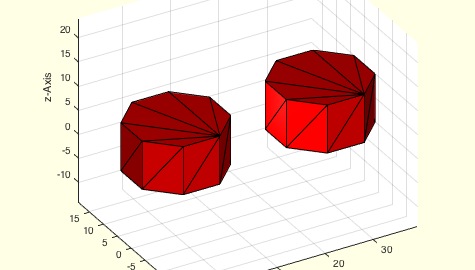
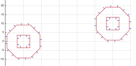
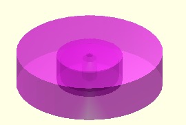
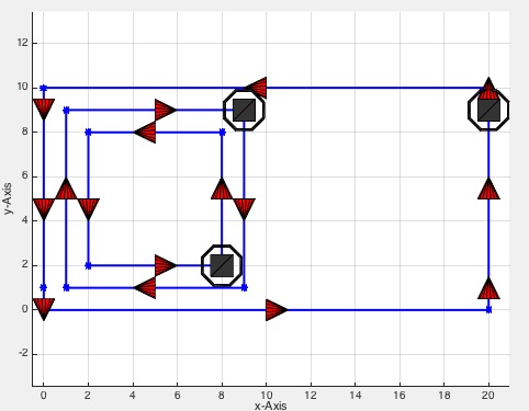
SGofCPLrot(CPL,n,rcorr)- returns a solid geometry from of a z-axis rotated closed polygon list |
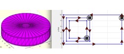 | % SGofCPLrot(CPL,n,rcorr) - returns a solid geometry from of a z-axis rotated closed polygon list % (by Tim Lueth, VLFL-Lib, 2014-NOV-29 as class: MODELING PROCEDURES) % % Basic modeling procedure such as SGofCPLz. An important feature of this % procedure is the insertion on contour points that make it possible to % separate the object easily in z. Nevertheless, if case that embeded % circles are rotated a remarkable number of new points are inserted at % the outside contour. (Status of: 2020-08-20) % % Introduced first in SolidGeometry 2.0 % % See also: SGofCPLsphere, SGbeating, SGofCPLz, SGofCPLT, CPLcutPez % % SG=SGofCPLrot(CPL,[n,rcorr]) % === INPUT PARAMETERS === % CPL: Radius-Z List % n: optional number of edges of the rotated polygon % rcorr: true = increase that R is on circle; default R is incircle % === OUTPUT RESULTS ====== % SG: Solid Geometry (SG.VL, SG.FL, SG.CPL) % % EXAMPLE: CPL=[0 0; 20 0; 20 10; 0 10; NaN NaN; 1 1; 9 1; 9 9; 1 9; NaN NaN; 2 2; 8 2; 8 8; 2 8 ]; % CPL(:,1)=CPL(:,1)+5 % CPL=PLcircle(10); % CPL=[0 10; 2 8; 0 5; 0 4; 4 1; 0 0]; % A=SGofCPLrot (CPL); SGchecker(A); % VLFLviewer(A); VLFLplotlight (1,0.5), view(-30,30); % figure(2); PLELofCPL(A.CPL); % % See also: SGofCPLsphere, SGbeating, SGofCPLz, SGofCPLT, CPLcutPez % % % Copyright 2014-2022 Tim C. Lueth |
VLFLofCPLrot(CPL,n,rcorr)- returns a solid geometry from of a radius-z list |
 | % VLFLofCPLrot(CPL,n,rcorr) - returns a solid geometry from of a radius-z list % (by Tim Lueth, VLFL-Lib, 2014-NOV-29 as class: MODELING PROCEDURES) % % Introduced first in SolidGeometry 2.0 % % See also: VLFLofCPLz, VLFLofCPL % % [VL,FL,CPL]=VLFLofCPLrot(CPL,[n,rcorr]) % === INPUT PARAMETERS === % CPL: Radius-Z List % n: number of edges of the prismatic cross section % rcorr: true = increase that R is on circle; default R is incircle % === OUTPUT RESULTS ====== % VL: Vertex list % FL: Facet list % CPL: Resulting contour polygon list % % EXAMPLE: Generating different solids by rotating a contour % CPL=[0 0; 20 0; 20 10; 0 10; NaN NaN; 1 1; 9 1; 9 9; 1 9; NaN NaN; 2 2; 8 2; 8 8; 2 8 ]; % CPL(:,1)=CPL(:,1)+5 % CPL=PLcircle(10); % CPL=[0 10; 2 8; 0 5; 0 4; 4 1; 0 0]; % [VL,FL,NCPL]=VLFLofCPLrot (CPL); % VLFLchecker(VL,FL); % VLFLviewer(VL,FL); VLFLplotlight (1,0.5), view(-30,30); PLELofCPL (NCPL); show % % See also: VLFLofCPLz, VLFLofCPL % % % Copyright 2014-2018 Tim C. Lueth |
CPLuniteCPL(CPL)- returns a correct directed closed polygon list from a undirected closed polygon list |
 | % CPLuniteCPL(CPL) - returns a correct directed closed polygon list from a undirected closed polygon list % (by Tim Lueth, VLFL-Lib, 2014-NOV-27 as class: ANALYTICAL GEOMETRY) % % ======================================================================= % OBSOLETE (2019-04-23) - USE 'CPLisccwcorrected' INSTEAD % ======================================================================= % % This fnctn returns a corrects ordered (cw/ccw) CPL. % To get the right order (ccw/cw) for a CPL 3D extrusion, use flip(CPL) % before. % A feature is that there are additional points on straight lines, that % help to separate the contour in y-axis into slices % May better use CPLofPL(CPLisccwcorrected(CPL)) instead! or % polyshape('simplifiy') (Status of: 2019-04-23) % % Introduced first in SolidGeometry 2.0 % % See also: [ CPLisccwcorrected ] ; CPLunite, CPLunitePLFL, % CPLisccwcorrected, CPLofPL % % CPL=CPLuniteCPL(CPL) % === INPUT PARAMETERS === % CPL: Closed polygon list (unidirected) % === OUTPUT RESULTS ====== % CPL: Closed polygon list (correctly) directed cw/ccw % % EXAMPLE: Show how the order of polygons can be corrected % CPL=[0 0; 20 0; 20 10; 0 10; NaN NaN; 1 1; 9 1; 9 9; 1 9; NaN NaN; 2 2; 8 2; 8 8; 2 8 ] % CPL=CPLuniteCPL(CPL); % CPL=flip(CPL); % PLELofCPL(CPL); % % See also: [ CPLisccwcorrected ] ; CPLunite, CPLunitePLFL, % CPLisccwcorrected, CPLofPL % % % Copyright 2014-2019 Tim C. Lueth |